 3GPP Explorer
Overview
This document specifies the interface between a UICC and a terminal, covering UICC physical characteristics and the electrical exchange of APDUs. It defines activation and reset procedures, transmission using T=0 and T=1, and a layered model for communication. It also specifies application and file structures, security features, commands, responses and application-independent files and procedures. Support for Logical Secure Element interfaces is included, enabling a UICC to host multiple logical secure elements; the administrative procedures and optional communication interfaces are out of scope.
- UICC-terminal interface
- APDU
- ISO/IEC 7816-3
- T=0
- T=1
- Logical Secure Elements
Overview generated automatically from the document's scope and outline. The document text is authoritative.
Changes since v17.1.0
37 clauses modified, 15 clauses added
Compared automatically clause by clause from the extracted text of both versions; differences only in layout, spacing or table cells are ignored. The documents are authoritative.
1 Scopemodified
…ICC APDU interface; communication commands and procedures for the UICC APDU interface; application independent files and protocols for the UICC APDU interface. … Starting from Release 17, the UICC may support Logical Secure Element interfaces, which allows it to host multiple logical secure elements. A special form of such a Logical Secure Element (LSE) is a logical UICC. Where required, the lower layers which represent the features common to all LSEs are denoted as LSE base. The applicability of the clauses in the present document to either the LSE base or to the logical UICC is given in the introduction of each affected clause. The administrative procedures, initial card management and optional communication interfaces between the UICC and terminal are not within the scope of the present document.
3.1 Termsmodified
…d data sent by the application layer in a case 3 or 4 Command Le: maximum length of data expected by the application layer in response to a case 2 or 4 Command … Logical Secure Element (LSE): secure element functionalities, applications and files grouped together to act like a secure element (e.g. UICC) when multiple logical secure element interfaces are supported Logical Secure element Interface (LSI): logical connection between an endpoint in the terminal and one logical secure element logical UICC: upper layers of the UICC which implement the logic for handling the commands, files and protocols Lr: length of data sent back to the terminal by the UICC in response to a case 2 or 4 Command LSE base: lower layers of the UICC which are common for all LSEs Luicc: exact length of data available in the UICC to be returned in response to the case 2 or 4 Command received by the UICC Master File (MF): unique mandatory… …
3.3 Abbreviationsmodified
…ol ISO International Organization for Standardization LCSI Life Cycle Status Information LEN LENgth LRC Longitudinal Redundancy Check LSB Least Significant Bit … LSE Logical Secure Element LSI Logical Secure element Interface MAC Message Authentication Code ME Mobile Equipment MF Master File MMI Man-Machine Interface MSA Master SA MSB Most Significant Bit NAA Network Access Applicati… …
4.0a Introductionadded
The provisions of clause 4 apply to the LSE base.
5.0a Introductionadded
The provisions of clause 5 apply to the LSE base.
6.0 Introductionadded
The provisions of clause 6 apply to the LSE base.
6.3.3 Global Interface bytesmodified
…ecured APDU - Platform to Platform required as defined in ETSI TS 102 484 [20] 1 - - - - - 1 - eUICC-related functions supported as defined in GSMA SGP.22 [33] … 1 1 LSIs supported (see clause 7.5) NOTE: Any other value is RFU.
7.0 Introductionmodified
The provisions of clause 7 apply to the LSE base with the following exceptions: The provisions of clause 7.4 apply in the context of the related command defined in clause 11. Clause 7 defines the transmission protocols used to exchange data between the terminal and the UICC. The structure and processing of commands initiated by the t… …
7.2.3.1.1 Information field sizemodified
The IFSC defines the maximum length of the information field of blocks that can be received by the UICC. The default value of the IFSC is 32 bytes another value may be indicated in TA3the first TA for T = 1 of the ATR. The IFSD defines the maximum length of the information field of blocks that the terminal can receive. IFSD has a default value of 32 bytes and may … …
7.2.3.1.2 Character waiting integermodified
CWI is used to calculate CWT and shall be in the range from 0 to 5. The value is set in bits b4 to b1 in TB3.the first TB for T = 1 of the ATR.
7.2.3.1.7 Error detection codemodified
The parameter tCiin the first TC for T = 1 in the ATR is used to define which error detection code to use. LRC shall be used (b1 = 0). All other bits in tCithe first TC for T = 1 of the ATR are RFU and shall be set to 0.
7.2.3.2.1.1 Node address bytemodified
The NAD-byte identifies the source and the intended destination of the block. The NAD may also be used to distinguish between different logicalLSIs connections if they coexist as well as to provide Vpp state control (bit b8 and b4). Since b8 and b4 are not used, they shall be coded as '0'. Below is the structure of the NAD-byte. Table 7.4: Node address byte b8 b7 b6 b5 b4 b3 b2 b1 Unused DAD Unused SAD InIf multiple LSIs are supported and the firstterminal blockand sentthe fromUICC agreed to use the terminal,NAD abyte logicalto connectionindicate the LSI, then the LSI is setidentified upby basedthe oncombination of SAD and DAD values using the addressesencoding in table 7.4a. Table 7.4a: LSI number encoding Terminal address UICC address SAD and(terminal DAD.to SubsequentUICC) blocksDAD with(terminal anto NADUICC) containingLSI number DAD (UICC to terminal) SAD (UICC to terminal) b3 b2 b1 b3 b2 b1 '00' 0 0 0 0 0 0 '01' 0 0 0 0 0 1 ... '07' 0 0 0 1 1 1 '08' 0 0 1 0 0 0 RFU 0 0 1 0 0 1 '09' 0 0 1 0 1 0 ... '1F' 1 0 0 0 1 0 NOTE 1: The use of the same pairvalue offor terminal and UICC addresses areis associatedRFU, withexcept for SAD = DAD = '0'. NOTE 2: Blocks transmitted from the terminal to the UICC use terminal address as the SAD value and the UICC address as the DAD value. Blocks transmitted from the UICC to the terminal using the same logicalUICC connection.address Onlyas the SAD value and the same terminal as the DAD value belong to the same LSI. If multiple LSI is not supported, only the default value SAD = DAD = 0 shall be supported. All other combinations are RFU.
7.3.2.0 General mechanismmodified
…s mapped to the information of an I-block according to the four different cases described below. Each case is described in detail in clauses 7.3.2.1 to 7.3.2.4. … If the UICC indicates in the ATR both support of LSIs and in the response to MANAGE LSI(configure LSIs) support for LSI selection using the NAD byte, the NAD byte may be used to select the LSI. If the NAD byte is used to select the LSI, the transmission of an APDU (starting with the first I-block of the C-APDU and ending with the last I-block of the R-APDU) on one LSI shall not be interleaved with any block of a different LSI. NOTE: Interleaving of blocks between different LSIs is FFS.
7.3.2.1 Case 1modified
C-APDU is mapped to the INF of the I-block without any changes:changes. Terminal UICC Application Layer (C-APDU) CLA INS P1 P2 Transport layer (C-TPDU, INF) CLA INS P1 P2 Command Processing Transport layer (R-TPDU, INF) SW1 | SW2… …
7.4.3 Application executionmodified
… 7.12. Table 7.12: Minimum time-out value for execution of commands Case Time-out The terminal indicates a maximum available power supply in the terminal power … 20 seconds supply of 20 seconds TERMINAL CAPABILITY command that is greater than or equal to the UICC Maximum Power Consumption as indicated in EFUMPC. The terminal is not able to supply the UICC Maximum Power Consumption as indicated in T_OP value from EFUMPC indicated in EFUMPC. UICC Maximum Power Consumption (EFUMPC) is not present on the UICC. Not specified Application providers are advised to give appropriate warnings to the… …
7.5 Logical secure element Interfacesadded
A UICC may support LSIs. If supported by the UICC, this shall be indicated in the ATR. LSIs provide a multiplexing mechanism which allows the terminal to communicate with multiple LSEs over one physical interface. LSIs supported by the UICC and the terminal shall be identified by consecutive numbers starting from zero. The maximum value for the LSI is '1F'. Management of LSIs is done via a dedicated command MANAGE LSI which allows: • selection of an LSI for subsequent APDUs (mandatory for protocol T = 0, optional for protocol T = 1); • resetting an LSE without affecting other LSEs; and • setup of the LSI configuration to be used during the card session. When the protocol T = 1 is used, the selection of an LSI may be performed using the NAD byte, as defined in clause 7.2.3.2.1.1. Terminal and UICC shall agree on using LSIs as follows: • The UICC indicates support for LSIs in the ATR. • If indicated by the UICC, the terminal shall indicate in PPS2 if LSIs shall be used for the card session. • If LSIs are used for the card session, LSI 0 is selected after the PPS. • Before sending a command on an LSI different from 0 or sending any other MANAGE LSI command, the terminal shall perform the setup of the LSI configuration by sending a MANAGE LSI (configure LSIs) APDU to the UICC. If a terminal uses a non-removable UICC and the LSI configuration to be used is pre-agreed between terminal and UICC (by a mechanism out of scope of the present document), the setup may be skipped. After the setup, the terminal can use the mechanisms for the management of LSIs.
8.0 Introductionadded
The provisions of clause 8 apply to the logical UICC with the following exceptions: • The provisions of clause 8.10 describe the concept of LSEs.
8.4.1 SELECT by File Identifier referencingmodified
…e. Therefore ADF1can be selected by using the FID '7FFF'. Table 8.1: File selection Last selected file Valid selections MF ADF1, DF1, EF1, EF-DIR DF1 MF, ADF1, … EF2,EF2 ADF1 MF, DF3, DF4, EF3 DF3 MF, ADF1, DF4, DF5, EF4 DF4 MF, ADF1, DF3, EF5, EF6 DF5 MF, ADF1, DF3, EF7 EF1 MF, ADF1, DF1, EF-DIR EF2 MF, ADF1, DF1 EF3 MF, ADF1, DF3, DF4 EF4 MF, ADF1, DF3, DF4, DF5,DF5 EF5 MF, ADF1, DF3, DF4, EF6 EF6 MF, ADF1, DF3, DF4, EF5 EF7 MF, ADF1, DF3, DF5
8.4.2 SELECT by path referencingmodified
…ning of the path Example selections any MF 'EF1', 'EF-DIR', 'DF1', 'DF1 | EF2' any MF '7FFF | DF3', '7FFF | DF3 | EF4', '7FFF | DF3 | DF5', '7FFF | DF3 | DF5 | … EF7'EF7', '7FFF | DF4', '7FFF | DF4 | EF5', '7FFF | DF4 | EF6, '7FFF | EF3' DF1 Current DF 'EF2' DF3 Current DF 'DF5', 'DF5 | EF7', 'EF4' DF4 Current DF 'EF5', 'EF6' DF5… …
8.6 Reservation of file Idsmodified
… DF and requests for allocation of DF or EF identifiers under the DFs shall be made to the responsible organization. The same should be done for DFs used by an … organization.organization: Elementary files: - Administrative use: '6F XX' in the DFs '7F 4X'; '4F XX' in the DFs '5F 1X', '5F2X'; '6F 1X' in the DFs '7F 10', '7F 20', '7F 21'; '4F… …
8.10 Logical secure elementsadded
A UICC may support several LSEs on the same physical element. Each LSE acts and is handled by the terminal like a separate SE. The terminal communicates with the different LSEs via LSIs. Each LSE operates logically independently from the others. As seen on the interface, each LSE has its own file system, its own applications, its own AIDs, its own independent security status, its own CAT session (which means that several of them can run interleaved in parallel on the different LSIs), and its own runtime environment. The terminal can switch between the LSEs by sending MANAGE LSI (select LSI) commands or by selecting the LSI via the NAD byte when using T = 1. The MANAGE LSI command also allows resetting an LSE. Such a reset shall be equivalent to a warm reset of the interface for a UICC not supporting LSEs. A cold reset or a warm reset of the physical interface results in resetting all LSEs. When the terminal receives a REFRESH proactive command with mode "UICC reset" on an LSI, the terminal shall reset only the corresponding LSE via a MANAGE LSI command. If the UICC supports the UICC-CLF interface as defined in ETSI TS 102 613 [19], this interface shall be assigned to at most one LSE. The ATRs returned in MANAGE LSI (reset LSE) for the different LSEs shall reflect the support of this interface by the LSE. The assigned LSE may be updated by the terminal using the MANAGE LSI (assign SWP) command. The assigned LSE does not change with a reset of the UICC and is also used for any communication that occurs while the interface defined in the present document is deactivated.
9.0 Introductionmodified
The provisions of clause 9 apply to the logical UICC with the following exceptions: The provisions of clause 9.6 describe the specific security features of LSEs. Every application that conforms to the present document may define security features in addition to the mandatory features defined in this clause.
9.5.1 Access condition mappingmodified
…'0B' '95' '01' '08' ADM2 'A4' '06' '83' '01' '0C' '95' '01' '08' ADM3 'A4' '06' '83' '01' '0D' '95' '01' '08' ADM4 'A4' '06' '83' '01' '0E' '95' '01' '08' ADM5 … Value Usage CRT Tag Len Key Ref Access condition Level Len Value Qualifier Len Val Tag Tag 'A4' '06' '83' '01' '11' '95' '01' '08' PIN Universal PIN 1 'XX' '06' '83' '01' '12-1E' '95' '01' '08' RFU (Global) 3 'A4' '06' '83' '01' '81' '95' '01' '08' Se… …
9.6 LSE isolationadded
Different LSEs on a UICC shall be isolated from each other. All features provided by an LSE shall be kept separate from those belonging to other LSEs: • file system; • applications; • AIDs; • CAT session; • security context; • runtime environment; • etc. The terminal shall also keep this isolation: • To reset an LSE, the dedicated logical reset mechanism shall be used. • If an LSE requests a REFRESH proactive command with mode UICC reset, only this LSE shall be reset using the dedicated logical reset mechanism.
10.0 Introductionadded
The provisions of clause 10 apply in the context of the commands defined in clause 11.
10.1.2 Coding of Instruction Bytemodified
…0' '14' MANAGE CHANNEL '0X' or '4X' or '6X' '70' MANAGE SECURE CHANNEL '0X' or '4X' or '6X' '73' TRANSACT DATA '0X' or '4X' or '6X' '75' SUSPEND UICC '80' '76' … COMMAND CLA INS Command APDUs GET IDENTITY '8X' or 'CX' or 'EX' '78' (see note) EXCHANGE CAPABILITIES '80' '7A' (see note) COMMANDMANAGE CLALSI INS'80' Command APDUs'7C' Transmission oriented APDUs applying to the above commands GET RESPONSE '0X' or '4X' or '6X' 'C0' NOTE: These INS values are also used by GlobalPlatform (for t… …
10.2.2 Status words of the commandsmodified
…LENGE TRANSACT DATA UPDATE BINARY RETRIEVE DATA AUTHENTICATE SUSPEND UICC READ RECORD ACTIVATE FILE GET IDENTITY READ BINARY UNBLOCK PIN CHANGE PIN DISABLE PIN … MANAGE LSI Status words ENABLE PIN CAPABILITY VERIFY PIN RESPONSE ENVELOPE INCREASE TERMINAL TERMINAL SET DATA CHANNEL STATUS SELECT FETCH 90 00 * * * * * * * * * * * * * * * * * * * * * * * * * * * * * * 91 XX * * * * * * * * * * * * * * * * * * * * * * * * * * * * 93 00 * 98 50 * 98 62 * * 62 00 * * * * * * * * * * * * * * * * * * * * * * * * * * * 62 81 * * 62 82 * * * 62 83 * * 62 85 * * 62 F1 * * * * 62 F2 * * 62 F3 * * 63 F1 * * * 63 F2 * 63 CX * * * * * * * * * 64 00 * * * * * * * * * * * * * * * * * * * * * * * * * * * * * * 65 00 * * * * * * * * * * * * * * * * * * * * * 65 81 * * * * * * * * * * * * * * 67 XX * * * * * * * * * * * * * * * * * * * * * * * * * * * * * * 68 00 * * * * * * * * * * * * * * * * * * * * * * * * * * * * * * 68 81 * * * * * * * * * * * * * * * * * * * * * * * * * * * * * * 68 82 * * * * * * * * * * * * * * * * * * * * * * * * * * * * * * 69 00 * * * * * * * * * * * * * * * * * * * * * * * * * * * * * 69 81 * * * * * * * * 69 82 * * * * * * * * * * * * * * 69 83 * * * * * 69 84 * * * * * * * * * * * * * * 69 85 * * * * * * * * * * * * * * * * * * 69 86 * * * * * * * * * * MANAGE SECURE TERMINAL PROFILE MANAGE CHANNEL SEARCH RECORD DEACTIVATE FILE UPDATE RECORD GET CHALLENGE TRANSACT DATA UPDATE BINARY RETRIEVE DATA AUTHENTICATE SUSPEND UICC READ RECORD ACTIVATE FILE GET IDENTITY READ BINARY UNBLOCK PIN CHANGE PIN DISABLE PIN MANAGE LSI Status words ENABLE PIN CAPABILITY VERIFY PIN RESPONSE ENVELOPE INCREASE TERMINAL TERMINAL SET DATA CHANNEL STATUS SELECT FETCH 69 89 * * * * * * * * * * * * * * * * * * * * * * * * * 6A 80 * * * * * * * * * * 6A 81 * * * * * * * * * * * * * * * * * * * * * * * * * * * * * * 6A 82 * * * * * * * * * * * 6A 83 * * * 6A 84 * * * 6A 86 * * * * * * * * * * * * * * * * * * * * * * * * * * * * * * 6A 87 * * * * 6A 88 * * * * * * * * 6B 00 * * * * * * * * * * * * * * * * * * * * * * * * * * * * * * 6E 00 * * * * * * * * * * * * * * * * * * * * * * * * * * * * * * 6F XX * * * * * * * * * * * * * * * * * * * * * * * * * * * * * * 92 XX * 98 63 * * 98 64 * The responses '91 XX', and '93 00' can only be given by a UICC to a termina… …
11.0 Introductionadded
The provisions of clause 11 apply to the logical UICC with the following exceptions: • MANAGE LSI applies to the LSE base as it is used to manage LSEs. • SUSPEND UICC is only applicable to a UICC not supporting LSEs.
11.1.1.4.3 File Descriptormodified
…aning 0 X - - - - - - File accessibility 0 0 - - - - - - Not shareable file 0 1 - - - - - - Shareable file 0 - X X X - - - File type 0 - 0 0 0 - - - Working EF … b8 b7 B6 b5 b4 b3 b2 b1 Meaning 0 - 0 0 1 - - - Internal EF 0 - 0 1 0 - - - 0 - 0 1 1 - - - 0 - 1 0 0 - - - RFU 0 - 1 0 1 - - - 0 - 1 1 0 - - - 0 - 1 1 1 0 0 0 DF or ADF 0 - - - - X X X EF str … inear fixed structure 0 - - - - 0 1 1 0 - - - - 1 0 0 RFU 0 - - - - 1 0 1 0 - - - - 1 1 0 Cyclic structure 0 - - - - 1 1 1 RFU 0 - 1 1 1 0 0 1 BER-TLV structure … b8 b7 B6 b5 b4 b3 b2 b1 Meaning 1 X X X X X X X RFU Data coding byte. Coding: The data coding byte is coded according to ISO/IEC 7816-4 [12]. The actual value shall not be checked nor used by… …
11.1.1.4.6.2 Application power consumptionmodified
…ort the power consumption indicated by the application. Byte(s) Description Value Length 1 Tag '81' 1 2 Length '03' 1 3 Supply voltage class at which the power … 1 consumption is 1 measured 4 Application power consumption '01' to '3C' 1 5 Power consumption reference frequency '0A' to 'FF' 1 The power consumption reference frequency is cod… …
11.1.1.4.6.9 Specific UICC environmental conditionsmodified
…her to evaluate this object and how to behave. Byte(s) Description Value Length 1 Tag '88' 1 2 Length '01' 1 3 Specific UICC environmental conditions byte (see … 1 table 11.7a) 1 Table 11.7a: Specific UICC environmental conditions byte b8 b7 b6 b5 b4 b3 b2 b1 Meaning - - - - - X X X Temperature Class 0 0 0 Standard temperature range - -… …
11.1.16.2 Command parameters and datamodified
…transmit previous block of authentication response data Command data: Byte(s) Description Length 1 to Lc TLV encapsulated authentication related data, possibly … Lc segmented (see note) Lc NOTE: The command data shall be specified by each application specific document. Response data (generic): Byte(s) Description Length 1 to Le TLV encapsulated a… …
11.1.19.2.0 Base codingmodified
….1.19.2.1 Extended logical channels terminal support '81' 11.1.19.2.2 Additional interfaces support '82' 11.1.19.2.3 Additional Terminal capability indications … '83' 11.1.19.2.4 related to eUICC '83' 11.1.19.2.4
11.1.19.2.4 Additional Terminal capability indications related to eUICCmodified
…ble 11.20b: Terminal capabilities for eUICC Byte(s) Description Value Length 1 Tag '83' 1 2 Length X 1 3 to X+2 Terminal capabilities for eUICC, see RSP Device … X Capabilities X in GSMA SGP.22 [33]
11.1.20.5.2 Command parameters and datamodified
…-bit AES in CBC mode as defined in ETSI TS 102 225 [21] 1 - - - - - - - Proprietary algorithm (known to both parties) - X X X X - - - RFU Only one bit shall be … indicated.indicated: - Coding of Byte 2 - Integrity mechanism (UIM): b8 b7 b6 b5 b4 b3 b2 b1 Meaning - - - - - - - 1 CRC32 as defined in ETSI TS 102 225 [21] - - - - - - 1 - MAC al… …
11.1.21.2 Command parameters and datamodified
…data: Secure channel number coding (P1): Table 11.30: Coding of P1 - Session control b8 b7 b6 b5 b4 b3 b2 b1 Meaning X X - - - - - - Session number - - 0 0 0 - … --RFU RFU - - - - - - X - - Command Data control 1: Command contains data 0: No command data - - - - - - X - Abort session 0 - Continue session 1 - Abort session - - - - … in the following way: Byte(s) Description Length 1 Secure channel data Tag 1 2 or Length 1 or 2 2 to 3 (3 to 3+X) or TRANSACT DATA command data as specified in … X (4 to 4+X) ETSI TS 102 484 [20] X (4 to 4+X) The same tag value shall be used within one transfer session. All data within subsequent TRANSACT DATA commands within the same session shall use the same tag … …
11.1.22.1 Functional descriptionmodified
…inal does not issue the command if the UICC suspension mechanism is not indicated as supported by the UICC in the UICC Maximum Power Consumption file (EFUMPC). … A UICC supporting LSEs shall not indicate support for the UICC suspension mechanism. A terminal supporting LSEs shall not use the UICC suspension mechanism defined in the present document on a UICC supporting LSEs. The terminal shall not use this mechanism if it supports an interface in addition to the interface defined in the present document (e.g. the UICC-CLF interface as defined in ETSI TS 102 613 [19]). The following P1 values are defined:defined. Table 11.34a: Coding of P1 b8 b7 b6 b5 b4 b3 b2 b1 Meaning - - - - - - - 0 Suspend the UICC - - - - - - - 1 Resume the UICC X X X X X X X - RFU (shall be set t… …
11.1.22.2.3 Command parameters and datamodified
…n proposed by terminal Le Length of the response data = '0A' Command data: Byte(s) Description Length 1 to 2 Minimum duration of the suspension proposed by the … 2 terminal. 2 3 to 4 Maximum duration of the suspension proposed by the 2 terminal. 2 Response data: Byte(s) Description Length 1 to 2 Maximum duration of the suspension negotiated by the 2 UICC 2 3 to 10 Resume token 8 Where all durations in the command and in the response are encoded as: Byte(s) Description Length 1 Time unit: 1 - 0: seconds - 1: minut… …
11.1.25 MANAGE LSIadded
11.1.25.1 Functional descriptionadded
This command is used to manage LSIs and LSEs. It provides the mechanism required for the multiplexing of the APDUs of different LSIs, each targeting a separate LSE, and thus enables multiple independent LSEs to reside on one UICC. It provides functionality for: • selecting an LSE for subsequent APDUs (see note 3); • resetting an LSE; • setting up the LSI configuration after power up or a reset of the physical interface; and • assigning the UICC-CLF interface to an LSE and retrieving the LSI of the LSE that has the UICC-CLF interface assigned. Unless the LSI configuration is pre-agreed (see clause 7.5), MANAGE LSI (configure LSIs) shall be used to setup the LSI configuration before sending a command on an LSI different from 0 or a different MANAGE LSI command. The terminal shall send the MANAGE LSI (configure LSIs) command not more than once in a card session. At the beginning of a card session, LSI 0 is selected. The terminal may select a different LSI using the MANAGE LSI (select LSI) APDU, indicating an LSI number up to the jointly supported maximum value. After a MANAGE LSI (select LSI) APDU, the indicated LSI is selected and subsequent ADPUs are handled by the LSE on this LSI until the next MANAGE LSI (select LSI), MANAGE LSI (reset LSE) or MANAGE LSI (assign SWP) APDU or a reset of the interface. A MANAGE LSI (reset LSE) APDU shall result in the selection and the resetting of the LSE on the indicated LSI and shall be equivalent to a warm reset for a UICC not supporting LSEs. NOTE 1: The LSI may or may not have been selected already before the MANAGE LSI (reset LSE) command is received. NOTE 2: In order to closely resemble the normal operation of a UICC, where the first data provided by the UICC is the ATR, the terminal may send the command MANAGE LSI (reset LSE) as the first APDU on each LSI at the beginning of each card session. NOTE 3: If T = 1 is supported, the selection of an LSI may alternatively be performed using the NAD byte, see clause 7.2.3.2.1.1. The MANAGE LSI (assign SWP) is used by the terminal to indicate the LSE that will handle the communication over the UICC-CLF interface. The terminal shall not assign that interface to an LSE, if the UICC-CLF interface is not indicated as supported in the ATR of that specific LSE. After assigning the interface to an LSE successfully, the LSE shall be used for handling the communication over the UICC-CLF interface until a new MANAGE LSI (assign SWP) command is received. This includes any communication that occurs after a UICC reset or while the interface defined in the present document is deactivated. A MANAGE LSI (assign SWP) also selects and resets the LSE that gets the UICC- CLF interface assigned. After assigning the UICC-CLF interface to an LSE, the terminal shall activate the UICC-CLF interface to handle the SYNC_ID verification process as described in ETSI TS 102 613 [19], clause 9.4.1. The terminal can retrieve the LSE that is currently assigned to handle the communication over the UICC-CLF interface using the MANAGE LSI (retrieve SWP) command. Input: • None or the LSI configuration supported by the terminal. Output: • None; or • the ATR of the LSE, or • the LSI configuration to be used in the card session, or • the LSI of the LSE that has the UICC-CLF interface assigned.
11.1.25.2 Command parameters and dataadded
Code Value CLA As specified in clause 10.1.1 INS As specified in clause 10.1.2 P1 LSI operation code, see table 11.34c P2 LSI number, range '00' to '1F' Lc Not present or length of subsequent data field Data Data according to P1 Le Not present or length of expected data Table 11.34c Coding of P1 b8 b7 b6 b5 b4 b3 b2 b1 Meaning 0 0 0 0 0 0 0 0 Select LSI - Lc and Le not present (see note 2) 0 0 0 0 0 0 0 1 Reset LSE - Lc not present, Le present and set to '00' 0 0 0 0 0 0 1 0 Assign SWP - Lc not present, Le present and set to '00' 0 0 0 0 0 0 1 1 Retrieve SWP - P2 set to '00', Lc not present, Le present and set to '00' 0 0 0 0 0 1 0 0 Configure LSIs - P2 set to '00', Lc and data present, Le present and set to '00' NOTE 1: All other values are RFU. NOTE 2: If the NAD byte is used to select the LSI, this command shall not be used by the terminal. Command data: • For select LSI, reset LSE, assign SWP and retrieve SWP, the command data is not present. • For reset LSE and assign SWP, if the NAD byte is used to select the LSI, the command shall be sent on the LSI indicated by P2. • For configure LSIs, the command data shall contain the values supported by the terminal: Byte(s) Description Value Length Status 1 Tag for highest LSI proposed by the terminal '80' 1 2 Length of next field 1 1 M 3 Highest LSI proposed by the terminal 1 4 Tag for LSI options supported by the terminal '81' 1 5 Length of next field 1 1 O 6 LSI options supported by the terminal, coding see table 11.34d 1 The UICC shall interpret any value for the highest LSI proposed by the terminal that is greater than the maximum value for the LSI defined in clause 7.5 as the maximum value itself. NOTE: This avoids interoperability issues if the maximum value for the LSI is increased in a future release of the present document. Table 11.34d Coding LSI options b8 b7 b6 b5 b4 b3 b2 b1 Meaning - - - - - - - x 1: LSI indication via NAD byte supported / used 0: LSI indication via NAD byte not supported / not used x x x x x x x - RFU, shall be set to 0 If the TLV for the LSI options is absent in the command or in the response, it shall be interpreted as all bits being set to 0. Tags '90' and '91' are reserved for GSMA SGP.22 [33]. The UICC shall ignore any additional TLV(s). Response data: • For select LSI, the response data shall be empty. • For reset LSE and assign SWP, the response data shall contain the ATR of the LSE. Byte(s) Description Value Length 1 Tag for ATR '80' 1 2 Length of next field N 1 3 to N+2 ATR value N For configure LSIs, the response data shall contain the LSI configuration supported by the UICC that can be used in the card session. Byte(s) Description Value Length Status 1 Tag for highest LSI to be used in the card session '80' 1 2 Length of next field 1 1 M 3 Highest LSI to be used in the card session 1 4 Tag for LSI options to be used in the card session '81' 1 5 Length of next field 1 1 O 6 LSI options to be used in the card session, coding see table 11.34d 1 The highest LSI in the response shall not be greater than the highest LSI value proposed by the terminal in the command. If both the terminal and the UICC support LSI indication via NAD byte, this option shall be used in the card session. Tags '90' and '91' are reserved for GSMA SGP.22 [33]. For retrieve SWP, the response shall contain the LSI of the LSE that has the UICC-CLF interface assigned. Byte(s) Description Value Length 1 Tag for LSE assigned to SWP '80' 1 2 Length of next field 1 1 3 LSI of the LSE assigned to SWP, or 'FF' if none is assigned 1
12.0 Introductionadded
The provisions of clause 12 apply in the context of the related command defined in clause 11.
12.1.1.1 Functional descriptionmodified
…minal shall send the GET RESPONSE command on the same logical channel before sending a command APDU in another logical channel. Otherwise, the response is lost. … This requirement equally applies for LSIs.
13.0 Introductionadded
The provisions of clause 13 apply to the logical UICC.
13.6 EFUMPC (UICC Maximum Power Consumption)modified
…erator defined time-out for the execution of any commands by the UICC if the terminal is not able to indicate it can supply the UICC maximum power consumption. … In case of a UICC supporting LSEs, the values of byte 1 and the value of bit 1 of byte 3 should be the same in all LSEs containing this EF. Table 13.8: EFUMPC at MF-level Identifier: '2F08' Structure: transparent Mandatory SFI: Mandatory File size: 5 bytes Update activity: low Access Conditions: REA… …
14.0 Introductionadded
The provisions of clause 14 apply to the logical UICC.
14.5.2 UICC presence detectionmodified
… the applications active during the card session. This procedure shall be used in addition to a mechanical or other device used to detect the removal of a UICC. … In case of a UICC supporting LSEs, this procedure shall be performed for each LSE that requires presence detection.
14.6.2 Proactive pollingmodified
…02 223 [4]). During a call the UICC presence detection applies. The default value for the proactive polling is the same as for the presence detection procedure. … In case of a UICC supporting LSEs, the terminal shall perform the proactive polling on every LSI where CAT was successfully initialized with the interval negotiated on each specific LSI.
15 Support of APDU-based UICC applications over USBmodified
NOTE: Support for LSIs on USB is FFS. If a card session is established over the Smart Card functional interface specified in ETSI TS 102 600 [18], the following provisions apply. Clauses 6.3, 7.4, 8… …
G.1 Sample content of EFARRmodified
This clause contains a set of access rule examples that are stored in EFEFARR. ARR. The access rules are referenced using tag '8B' in the FCP. The following definitions apply: the application PIN is referred to as PIN Appl. 1 global (key refere … 1 ACTIVATE '84' '01' '32' 'A4' '06' '83' '01' '81' '95' '01' '08' global INCREASE Table G.2: DFTelecom Access Rule References Value Value ARR Appli- Access AM_ … SC_DOCSC_DOCRT Security SC_DOCSC_DOCRT Key Usage SC_DOCSC_DOCRT Key Usage L V L L L Record cable Condition DO RT Tag Condition RT Tag Ref L V Qualifier L V RT Tag Ref L V Qualifier L V Tag Tag Tag Tag 01 EF READ '80' '01' '01' '90' ALW '00' - - - - - - - - - - - - 02 EF READ '80' '01' '01' '90' ALW '00' UPDATE '80' '01' '02' 'A0' PIN Appl 1 global '10' 'A4' '06' '83' '01' '01' '95' '01' '08' 'A4' '06' '83' '01' '02' '95' '01' '08' DEACTIVATE/ '80' '01' '18' 'A4' global OR PIN Appl 2 '06' '83' '01' '0Z' '95' '01' 'XX' ACTIVATE Appl 2 Level 5 03 EF READ '80' '01' '01' 'A0' PIN Appl 1 global '10' 'A4' '83' '01' '01' '95' '01' '08' 'A4' '06' '83' '01' '02' '95' '01' '08' UPDATE/ '80' '01' '1A'' 'A4' global OR PIN Appl 2 '06' '83' '01' '0Z' '95' '01' 'XX' DEACTIVATE/ LevelAppl 52 ACTIVATE Level 5 04 EF READ/UPDATE '80' '01' '03' 'A0' PIN Appl 1 global '10' 'A4' '83' '01' '01' '95' '01' '08' 'A4' '06' '83' '01' '02' '95' '01' '08' DEACTIVATE/ '80' '01' '18' 'A4' global OR PIN Appl 2 '06' '83' '01' '0Z' '95' '01' 'XX' ACTIVATE Appl 2 Level 5 05 EF READ '80' '01' '01' '90' ALW '00' UPDATE/ '80' '01' '1A'' 'A4' Level 5 '06' '83' '01' '0Z' '95' '01' 'XX' DEACTIVATE/ ACTIVATE 06 EF READ/ '80' '01' '13' 'A0' PIN Appl 1 global '10' 'A4' '83' '01' '01' '95' '01' '08' 'A4' '06' '83' '01' '02' '95' '01' '08' UPDATE/ global OR PIN ACTIVATE Appl 2 ACTIVATE DEACTIVATE '80' '01' '08' 'A4' '06' '83' '01' '0Z' '95' '01' 'XX' Level 5 07 EF READ/UPDATEREAD/UPDATE/ '80' '01' '1B' 'A4' Level 5 '06' '83' '01' '0Z' '95' '01' 'XX' / DEACTIVATE/ ACTIVATE
K.2 PIN state transition between logical channelsmodified
… ↓ ↓ ('02') #28 DISABLE PIN ('02' → ↓ ↓ D (R) ↓ ↓ ↓ ↓ ↓ ↓ ↓ — D '08' 00 ↓ ↓ ↓ ↓ ↓ — ↓ ↓ '11') #29 VERIFY PIN ↓ ↓ ↓ V ↓ ↓ ↓ ↓ ↓ ↓ — ↓ ↓ ↓ ↓ ↓ ↓ ↓ ↓ — ↓ ↓ ('11') … #30 ATR ↓ ↓ ↓ N ↓ ↓ — MF MF ↓ D ↓ ↓ ↓ Logical channel #0 Logical channel #1 Security status PIN status DO in the FCP PIN status DO in the FCP PIN verification Current Usage SE Current Usage SE PIN s … PIN PIN PIN PIN PIN PIN AD PIN PIN PIN PIN channel #0 channel #1 ADF DF File DF File '11' '01' '02' '11' '01' '02' '11' '01' '02' ('11') F '11' '01' '02' ('11') … #30 ATR ↓ ↓ ↓ N ↓ ↓ — MF MF ↓ D ↓ ↓ ↓ #31 SELECT ↓ ↓ ↓ ↓ ↓ ↓ — ↓ ↓ ↓ ↓ ↓ ↓ ↓ MF #32 SELECT ADF ADF ADF by DF-name ↓ ↓ ↓ ↓ ↓ ↓ ↓ — ↓ ↓ ↓ (B) (B) (B) (B) #33 MANAGE CH. ↓ ↓ ↓ ↓ ↓ ↓ ↓ ↓ ↓ ↓ — ↓ ↓ ↓ — … …
N Change historymodified
The table below indicates all changes requests (CR) applied to the present document since it was created by TC SCP.SET (former TC SCP). Change history Date Meeting TC SCP Doc. CR Rv Cat Subject/Comment Old New 2000-08 SCP-02 9-00-0289 - - First draft created. Technical content is identical to 0. … 0.0 17.1.0 operating conditions 2021-12 SCP-103 SCP(21)000212r1 352 1 F Removal of inconsistency about the supported form 17.0.0 17.1.0 factors for the terminal … 2022-03 SET-104 SET(22)000037 353 D Clarification of ATR bytes for T=1 17.1.0 17.2.0 2022-07 SET-106 SET(22)000103r1 354 B Support of 32 LSIs in T=1 compliant ISO7816-3 17.1.0 17.2.0
Contents
- Foreword
- Modal verbs terminology
- Introduction
- 1 Scope
- 2 References
- 2.1 Normative references
- 2.2 Informative references
- 3 Definition of terms, symbols, abbreviations and coding conventions
- 3.1 Terms
- 3.2 Symbols
- 3.3 Abbreviations
- 3.4 Coding conventions
- 4 Physical characteristics
- 4.0a Introduction
- 4.0 UICC Form Factors
- 4.0.0 Generic requirements
- 4.0.1 ID-1 UICC
- 4.0.2 Plug-in UICC
- 4.0.3 Mini-UICC
- 4.0.4 4FF
- 4.1 ID-1 UICC
- 4.2 Plug-in UICC
- 4.3 Mini-UICC
- 4.4 Environmental conditions for card operation and storage
- 4.4.0 Standard UICC environmental conditions
- 4.4.1 Specific UICC environmental conditions
- 4.5 Contacts
- 4.5.1 Provision of contacts
- 4.5.2 Contact activation and deactivation
- 4.5.3 Inactive contacts
- 4.5.4 Contact pressure
- 5 Electrical specifications of the UICC - Terminal interface
- 5.0a Introduction
- 5.0 General requirements
- 5.1 Class A operating conditions
- 5.1.1 Supply voltage Vcc (contact C1)
- 5.1.2 Reset (RST) (contact C2)
- 5.1.3 Programming voltage Vpp (contact C6)
- 5.1.4 Clock CLK (contact C3)
- 5.1.5 I/O (contact C7)
- 5.2 Class B operating conditions
- 5.2.1 Supply voltage Vcc (contact C1)
- 5.2.2 Reset (RST) (contact C2)
- 5.2.3 Clock CLK (contact C3)
- 5.2.4 I/O (contact C7)
- 5.3 Class C operating conditions
- 5.3.1 Supply voltage Vcc (contact C1)
- 5.3.2 Reset (RST) (contact C2)
- 5.3.3 Clock CLK (contact C3)
- 5.3.4 I/O (contact C7)
- 5.4 Class D operating conditions
- 5.4.0 General
- 5.4.1 Supply voltage Vcc (contact C1)
- 5.4.2 Reset (RST) (contact C2)
- 5.4.3 Clock CLK (contact C3)
- 5.4.4 I/O (contact C7)
- 6 Initial communication establishment procedures
- 6.0 Introduction
- 6.1 UICC activation and deactivation
- 6.2 Supply voltage switching
- 6.2.0 UICC activation voltage
- 6.2.1 Supply voltage classes
- 6.2.2 Power consumption of the UICC during ATR
- 6.2.3 Application related electrical parameters
- 6.3 Answer To Reset content
- 6.3.0 Introduction
- 6.3.1 Coding of historical bytes
- 6.3.2 Speed enhancement
- 6.3.3 Global Interface bytes
- 6.4 PPS procedure
- 6.5 Reset procedures
- 6.5.1 Cold reset
- 6.5.2 Warm reset
- 6.5.3 Reaction to resets
- 6.6 Clock stop mode
- 6.7 Bit/character duration and sampling time
- 6.8 Error handling
- 6.9 Compatibility
- 7 Transmission protocols
- 7.0 Introduction
- 7.1 Physical layer
- 7.2 Data link layer
- 7.2.0 Introduction
- 7.2.1 Character frame
- 7.2.2 Transmission protocol T = 0
- 7.2.3 Transmission protocol T = 1
- 7.3 Transport layer
- 7.3.0 Introduction
- 7.3.1 Transportation of an APDU using T = 0
- 7.3.2 Transportation of a APDU using T = 1
- 7.4 Application layer
- 7.4.0 Overall description
- 7.4.1 Exchange of APDUs
- 7.4.2 CAT layer
- 7.4.3 Application execution
- 7.5 Logical secure element Interfaces
- 8 Application and file structure
- 8.0 Introduction
- 8.1 UICC application structure
- 8.2 File types
- 8.2.0 Introduction
- 8.2.1 Dedicated files
- 8.2.2 Elementary files
- 8.3 File referencing
- 8.4 Methods for selecting a file
- 8.4.0 Default state after UICC activation and ATR
- 8.4.1 SELECT by File Identifier referencing
- 8.4.2 SELECT by path referencing
- 8.4.3 Short File Identifier (SFI)
- 8.5 Application characteristics
- 8.5.0 Application selection types
- 8.5.1 Explicit application selection
- 8.5.2 Application session activation
- 8.5.3 Application session termination
- 8.5.4 Application session reset
- 8.5.5 Void
- 8.6 Reservation of file Ids
- 8.7 Logical channels
- 8.8 Shareable versus not-shareable files
- 8.9 Secure channels
- 8.10 Logical secure elements
- 9 Security features
- 9.0 Introduction
- 9.1 Supported security features
- 9.2 Security architecture
- 9.2.0 Overview and basic rules
- 9.2.1 Security attributes
- 9.2.2 Access mode
- 9.2.3 Security condition
- 9.2.4 Access rules
- 9.2.5 Compact format
- 9.2.6 Expanded format
- 9.2.7 Access rule referencing
- 9.3 Security environment
- 9.3.0 Description
- 9.3.1 Definition of the security environment
- 9.3.2 Logical Channels and Security Environment
- 9.4 PIN definitions
- 9.4.0 Introduction
- 9.4.1 Universal PIN
- 9.4.2 Application PIN
- 9.4.3 Local PIN
- 9.4.4 PINs and logical channels
- 9.5 PIN and key reference relationship
- 9.5.0 Introduction
- 9.5.1 Access condition mapping
- 9.5.2 PIN status indication
- 9.6 LSE isolation
- 10 Structure of commands and responses
- 10.0 Introduction
- 10.1 Command APDU
- 10.1.0 Structure and case
- 10.1.1 Coding of Class Byte
- 10.1.2 Coding of Instruction Byte
- 10.1.3 Coding of parameter bytes
- 10.1.4 Coding of Lc byte
- 10.1.5 Coding of data part
- 10.1.6 Coding of Le byte
- 10.2 Response APDU
- 10.2.0 Structure
- 10.2.1 Status conditions returned by the UICC
- 10.2.2 Status words of the commands
- 10.3 Logical channels
- 11 Commands
- 11.0 Introduction
- 11.1 Generic commands
- 11.1.0 Introduction
- 11.1.1 SELECT
- 11.1.2 STATUS
- 11.1.3 READ BINARY
- 11.1.4 UPDATE BINARY
- 11.1.5 READ RECORD
- 11.1.6 UPDATE RECORD
- 11.1.7 SEARCH RECORD
- 11.1.8 INCREASE
- 11.1.9 VERIFY PIN
- 11.1.10 CHANGE PIN
- 11.1.11 DISABLE PIN
- 11.1.12 ENABLE PIN
- 11.1.13 UNBLOCK PIN
- 11.1.14 DEACTIVATE FILE
- 11.1.15 ACTIVATE FILE
- 11.1.16 AUTHENTICATE
- 11.1.17 MANAGE CHANNEL
- 11.1.18 GET CHALLENGE
- 11.1.19 TERMINAL CAPABILITY
- 11.1.20 MANAGE SECURE CHANNEL
- 11.1.21 TRANSACT DATA
- 11.1.22 SUSPEND UICC
- 11.1.23 GET IDENTITY
- 11.1.24 EXCHANGE CAPABILITIES
- 11.1.25 MANAGE LSI
- 11.2 CAT commands
- 11.2.1 TERMINAL PROFILE
- 11.2.2 ENVELOPE
- 11.2.3 FETCH
- 11.2.4 TERMINAL RESPONSE
- 11.3 Data Oriented commands
- 11.3.0 Overview and generic mechanism
- 11.3.1 RETRIEVE DATA
- 11.3.2 SET DATA
- 12 Transmission oriented commands
- 12.0 Introduction
- 12.1 T = 0 specific commands
- 12.1.1 GET RESPONSE
- 13 Application independent files
- 13.0 Introduction
- 13.1 EFDIR
- 13.2 EFICCID (ICC Identification)
- 13.3 EFPL (Preferred Languages)
- 13.4 EFARR (Access Rule Reference)
- 13.5 DFCD (Configuration Data)
- 13.5.0 Introduction
- 13.5.1 EFLAUNCH PAD
- 13.5.2 EFICON
- 13.6 EFUMPC (UICC Maximum Power Consumption)
- 14 Application independent protocol
- 14.0 Introduction
- 14.1 File related procedures
- 14.1.1 Reading an EF
- 14.1.2 Updating an EF
- 14.1.3 Increasing an EF
- 14.2 PIN related procedures
- 14.2.0 Overview
- 14.2.1 PIN verification
- 14.2.2 PIN value substitution
- 14.2.3 PIN disabling
- 14.2.4 PIN enabling
- 14.2.5 PIN unblocking
- 14.3 Application selection procedures
- 14.3.1 Application selection by use of the EFDIR file
- 14.3.2 Direct application selection
- 14.3.3 Direct application selection with partial AID
- 14.4 General application related procedures
- 14.4.1 Application session activation
- 14.4.2 UICC application interrogation
- 14.4.3 UICC application session termination
- 14.5 Miscellaneous procedures
- 14.5.1 UICC activation
- 14.5.2 UICC presence detection
- 14.5.3 UICC preferred language request
- 14.5.4 UICC logical channels
- 14.5.5 Power negotiation
- 14.5.6 UICC suspension
- 14.6 CAT related procedures
- 14.6.0 Scope of CAT related procedures
- 14.6.1 CAT Initialization procedure
- 14.6.2 Proactive polling
- 14.6.3 Support of commands
- 14.6.4 Support of response codes
- 14.6.5 Independence of applications and CAT tasks
- 14.6.6 Use of BUSY status response
- 14.6.7 Additional processing time
- 15 Support of APDU-based UICC applications over USB
- Annex A (normative):
- UCS2 coding of Alpha fields for files residing on the UICC
- Annex B (informative): Main states of a UICC
- Annex C (informative):
- APDU protocol transmission examples
- C.1 Exchanges Using T = 0
- C.1.0 Overview
- C.1.1 Case 1 command
- C.1.2 Case 2 command
- C.1.3 Case 3 command
- C.1.4 Case 4 command
- C.1.5 Case 2 commands Using the '61' and '6C' procedure bytes
- C.1.6 Case 4 command Using the '61' procedure byte
- C.1.7 Case 4 command with warning condition
- Annex D (informative): ATR examples
- Annex E (informative):
- Security attributes mechanisms and examples
- E.1 Coding
- E.2 Compact format
- E.2.0 Coding
- E.2.1 AM byte
- E.2.2 SC byte
- E.2.3 Examples
- E.3 Expanded format
- E.3.0 Coding
- E.3.1 AM_DO
- E.3.2 SC_DO
- E.3.3 Access rule referencing
- E.3.4 Examples
- Annex F (informative):
- Example of contents of EFARR '2F06'
- F.1 Sample content of the EFARR
- Annex G (informative):
- Access Rules Referencing (ARR)
- G.1 Sample content of EFARR
- G.2 Example of access rule referencing with SE ID
- Annex H (normative):
- List of SFI Values assigned in ETSI TS 102 221
- H.1 List of SFI Values at the MF Level
- Annex I (informative): Resets and modes of operation
- Annex J (informative): Example of the use of PINs
- J.1 Application having several ADFs
- J.2 Two applications with two different security contexts
- Annex K (informative):
- Examples of the PIN state transition on multi verification capable UICC
- K.0 Context
- K.1 PIN state transition on the single logical channel
- K.2 PIN state transition between logical channels
- Annex L (informative):
- Examples of SET DATA and RETRIEVE DATA usage
- L.1 Examples of SET DATA and RETRIEVE DATA usage
- L.2 Examples of RETRIEVE DATA usage with transport protocol T = 0
- Annex M (informative):
- Examples of ODD AUTHENTICATE instruction code usage
- M.1 Examples of ODD AUTHENTICATE instruction code usage at applicative level
- M.2 Examples of ODD AUTHENTICATE instruction code usage with transport protocol T = 0
- Annex N (informative): Change history
- History
- Intellectual Property Rights
- Essential patents
- Trademarks
Foreword
This Technical Specification (TS) has been produced by ETSI Technical Committee Secure Element Technologies (SET).
It is based on work originally done in the 3GPP in TSG-terminals WG3.
The contents of the present document are subject to continuing work within TC SET and may change following formal TC SET approval. If TC SET modifies the contents of the present document, it will then be republished by ETSI with an identifying change of release date and an increase in version number as follows:
Version x.y.z
where:
- x the first digit:
- 0 early working draft;
- 1 presented to TC SET for information;
- 2 presented to TC SET for approval;
- 3 or greater indicates TC SET approved document under change control.
- y the second digit is incremented for all changes of substance, i.e. technical enhancements, corrections, updates, etc.
- z the third digit is incremented when editorial only changes have been incorporated in the document.
Modal verbs terminology
In the present document "shall", "shall not", "should", "should not", "may", "need not", "will", "will not", "can" and "cannot" are to be interpreted as described in clause 3.2 of the ETSI Drafting Rules (Verbal forms for the expression of provisions).
"must" and "must not" are NOT allowed in ETSI deliverables except when used in direct citation.
Introduction
The present document defines a generic Terminal/Integrated Circuit Card (ICC) interface.
The aim of the present document is to ensure interoperability between an ICC and a terminal independently of the respective manufacturer, card issuer or operator. The present document does not define any aspects related to the administrative management phase of the ICC. Any internal technical realization of either the ICC or the terminal is only specified where these are reflected over the interface.
Application specific details for applications residing on an ICC are specified in the respective application specific documents. The Universal Subscriber Identity Module (USIM)-application for 3G telecommunication networks is specified in ETSI TS 131 102 [2].
1 Scope
The present document specifies the interface between the UICC and the terminal.
The present document specifies:
- the requirements for the physical characteristics of the UICC;
- the electrical interface for exchanging APDUs between the UICC and the terminal, based on ISO/IEC 7816-3 [11];
- the initial communication establishment and the transport protocols for this interface;
- a model which serves as a basis for the logical structure of the UICC APDU interface;
- communication commands and procedures for the UICC APDU interface;
- application independent files and protocols for the UICC APDU interface.
Starting from Release 17, the UICC may support Logical Secure Element interfaces, which allows it to host multiple logical secure elements. A special form of such a Logical Secure Element (LSE) is a logical UICC. Where required, the lower layers which represent the features common to all LSEs are denoted as LSE base. The applicability of the clauses in the present document to either the LSE base or to the logical UICC is given in the introduction of each affected clause.
The administrative procedures, initial card management and optional communication interfaces between the UICC and terminal are not within the scope of the present document.
2 References
2.1 Normative references
References are either specific (identified by date of publication and/or edition number or version number) or non-specific. For specific references, only the cited version applies. For non-specific references, the latest version of the referenced document (including any amendments) applies.
- In the case of a reference to a TC SET document, a non-specific reference implicitly refers to the latest version of that document in the same Release as the present document.
Referenced documents which are not found to be publicly available in the expected location might be found at https://docbox.etsi.org/Reference.
NOTE: While any hyperlinks included in this clause were valid at the time of publication, ETSI cannot guarantee their long term validity.
The following referenced documents are necessary for the application of the present document.
- ETSI TS 123 038: "Digital cellular telecommunications system (Phase 2+) (GSM); Universal Mobile Telecommunications System (UMTS); LTE; Alphabets and language-specific information (3GPP TS 23.038)".
- ETSI TS 131 102: "Universal Mobile Telecommunications System (UMTS); LTE; 5G; Characteristics of the Universal Subscriber Identity Module (USIM) application (3GPP TS 31.102)".
- ETSI TS 101 220: "Smart Cards; ETSI numbering system for telecommunication application providers".
- ETSI TS 102 223: "Smart Cards; Card Application Toolkit (CAT)".
- Recommendation ITU-T E.118: "The international telecommunication charge card".
| [6] | ISO 639 (all parts): "Codes for the representation of names of languages". |
| [7] | ISO/IEC 7810: "Identification cards -- Physical characteristics". |
| [8] | ISO/IEC 7811-1: "Identification cards -- Recording technique -- Part 1: Embossing". |
| [9] | ISO/IEC 7816-1: "Identification cards -- Integrated circuit cards -- Part 1: Cards with contacts - Physical characteristics". |
| [10] | ISO/IEC 7816-2: "Identification cards -- Integrated circuit cards -- Part 2: Cards with contacts - Dimensions and location of the contacts". |
| [11] | ISO/IEC 7816-3: "Identification cards -- Integrated circuit cards -- Part 3: Cards with contacts - Electrical interface and transmission protocols". |
| [12] | ISO/IEC 7816-4: "Identification cards -- Integrated circuit cards -- Part 4: Organization, security and commands for interchange". |
| [13] | Void. |
| [14] | Void. |
| [15] | Void. |
| [16] | Void. |
| [17] | ISO/IEC 10646: "Information technology -- Universal Coded Character Set (UCS)". |
| [18] | ETSI TS 102 600: "Smart Cards; UICC-Terminal interface; Characteristics of the USB interface". |
| [19] | ETSI TS 102 613: "Smart Cards; UICC - Contactless Front-end (CLF) Interface; Physical and data link layer characteristics". |
| [20] | ETSI TS 102 484: "Smart Cards; Secure channel between a UICC and an end-point terminal". |
| [21] | ETSI TS 102 225: "Smart Cards; Secured packet structure for UICC based applications". |
| [22] | ETSI TS 124 008: "Digital cellular telecommunications system (Phase 2+) (GSM); Universal Mobile Telecommunications System (UMTS); LTE; 5G; Mobile radio interface Layer 3 specification; Core network protocols; Stage 3 (3GPP TS 24.008)". |
| [23] | JEDEC JESD22-A101D.01: "Steady-State Temperature-Humidity Bias Life Test". |
| [24] | OMA-ERELD- Smartcard-Web-Server-V1-1-20090512-A: "Enabler Release Definition for Smartcard-Web-Server". Approved Version 1.1 - 12 May 2009 (OMA). |
| [25] | ISO/IEC 15948:2004: "Information technology -- Computer graphics and image processing -- Portable Network Graphics (PNG): Functional specification". |
| [26] | IETF RFC 2046: "Multipurpose Internet Mail Extensions (MIME) Part Two: Media Types". |
| NOTE: | Available from http://www.ietf.org/rfc/rfc2046.txt. |
| [27] | ETSI TS 102 671: "Smart Cards; Machine to Machine UICC; Physical and logical characteristics". |
| [28] | Void. |
| [29] | ETSI TS 102 226: "Smart Cards; Remote APDU structure for UICC based applications". |
| [30] | Void. |
| [31] | ISO/IEC 9797-1:2011: "Information technology -- Security techniques -- Message Authentication Codes (MACs) -- Part 1: Mechanisms using a block cipher". |
| [32] | ETSI TS 102 222: "Integrated Circuit Cards (ICC); Administrative commands for telecommunications applications". |
| [33] | GSMA SGP.22: "RSP Technical Specification". |
- ETSI TS 103 666-1: "Smart Secure Platform (SSP); Part 1: General characteristics".
2.2 Informative references
References are either specific (identified by date of publication and/or edition number or version number) or non-specific. For specific references, only the cited version applies. For non-specific references, the latest version of the referenced document (including any amendments) applies.
- In the case of a reference to a TC SET document, a non-specific reference implicitly refers to the latest version of that document in the same Release as the present document.
NOTE: While any hyperlinks included in this clause were valid at the time of publication, ETSI cannot guarantee their long term validity.
The following referenced documents are not necessary for the application of the present document but they assist the user with regard to a particular subject area.
- [i.1] GlobalPlatform: "GlobalPlatform Card Specification Version 2.3.1".
NOTE: Availabe at http://www.globalplatform.org/.
- [i.2] GlobalPlatform: "Card Specification Version 2.3 - Amendment D: Secure Channel Protocol 03" Version 1.2.
3 Definition of terms, symbols, abbreviations and coding conventions
3.1 Terms
For the purposes of the present document, the following terms apply:
4FF: fourth form factor (format) of UICC
access conditions: set of security attributes associated with a file
ADM: access condition to an EF which is under the control of the authority which creates this file
application: set of security mechanisms, files, data and protocols (excluding transmission protocols)
NOTE: An application can be a first level application and/or a second level application.
application DF: entry point to an application
application protocol: set of procedures required by the application
bearer independent protocol: mechanism by which the terminal provides the UICC with access to the data bearers supported by the terminal and the network
NOTE: Part of CAT.
Card Application Toolkit (CAT): As specified in ETSI TS 102 223 [4].
card session: link between the card and the external world, using APDUs, starting with the ATR and ending with a subsequent reset or a deactivation of the card
NOTE: A card session may take place either over the electrical interface specified in the present document or over the Smart Card functional interface specified in ETSI TS 102 600 [18].
channel session: link between the card and the external world during a card session on a given logical channel, starting with the opening of the logical channel and ending with the closure of the logical channel or the termination of the card session
class A operating conditions: terminal or a smart card operating at 5 V ± 10 %
class B operating conditions: terminal or a smart card operating at 3 V ± 10 %
class C operating conditions: terminal or a smart card operating at 1,8 V ± 10 %
class D operating conditions: terminal or a smart card operating at 1,2 V ± 0,1 V
current directory: latest MF, DF or ADF selected
current EF: latest EF selected
current file: current EF, if an EF is selected, else the current directory
Data Object (DO): information coded as TLV object(s), i.e. consisting of a Tag, a Length and a Value part
Dedicated File (DF): file containing access conditions and, optionally, Elementary Files (EFs) or other Dedicated Files (DFs)
directory: general term for MF, DF and ADF
Elementary File (EF): file containing access conditions and data and no other files
file: directory or an organized set of bytes or records in the UICC
file identifier: 2 bytes which address a file in the UICC
first level application: selectable application that is indicated in EF DIR under the MF
EXAMPLE: A USIM application.
function: contains a command and a response pair
GSM session: part of the card session dedicated to the GSM operation
ID-1 UICC: UICC having the format of an ID-1 card
NOTE: See ISO/IEC 7816-1 [9].
Lc: length of command data sent by the application layer in a case 3 or 4 Command
Le: maximum length of data expected by the application layer in response to a case 2 or 4 Command
Logical Secure Element (LSE): secure element functionalities, applications and files grouped together to act like a secure element (e.g. UICC) when multiple logical secure element interfaces are supported
Logical Secure element Interface (LSI): logical connection between an endpoint in the terminal and one logical secure element
logical UICC: upper layers of the UICC which implement the logic for handling the commands, files and protocols
Lr: length of data sent back to the terminal by the UICC in response to a case 2 or 4 Command
LSE base: lower layers of the UICC which are common for all LSEs
Luicc: exact length of data available in the UICC to be returned in response to the case 2 or 4 Command received by the UICC
Master File (MF): unique mandatory file containing access conditions and optionally DFs and/or EFs
mini-UICC: third form factor (format) of UICC
multi-application capable terminal: terminal that can support more than one first level application with possibly separate user verification requirements for each application
multi-application card: card that can have more than one selectable application
multi-session card: card that supports more than one concurrent selectable application session during a card session
multi-verification capable UICC: card that can have more than one first level application and may support separate user verification requirements for each application
normal USIM operation: relating to general, PIN related, 3G and or GSM security and subscription related procedures
padding: one or more bits appended to a message in order to cause the message to contain the required number of bits or bytes
plug-in UICC: second form factor (format) of UICC
proactive UICC: UICC which is capable of issuing commands to the terminal
NOTE: Part of CAT.
proactive UICC session: sequence of related CAT commands and responses which starts with the status response '91XX' (proactive command pending) and ends with a status response of '90 00' (normal ending of command) after Terminal Response
NOTE: Part of CAT.
record: string of bytes within an EF handled as a single entity
record number: number which identifies a record within an EF
record pointer: pointer which addresses one record in an EF
removable UICC: UICC which is easily accessible or replaceable, is intended to be removed or replaced in the terminal
second level application: application which can only be activated during the session of a first level application
NOTE: A second level application may have an AID. This AID is not to be stored in EF(DIR) unless it is also a first level application.
selectable application: application that is selectable by an AID according to the process described in ISO/IEC 7816-4 [12] over the terminal-UICC interface
selectable application session: link between the application and the external world during a card session starting with the application selection and ending with de-selection or termination of the card session
single verification capable UICC: card that only supports one user verification requirement for all first level applications
state H: high state on the I/O line (Vcc)
state L: low state on the I/O line (Gnd)
transport layer: layer responsible for transporting Secured Packets through the network
type 1 UICC: UICC which always enters the negotiable mode after a warm reset
type 2 UICC: UICC which always enters the specific mode after a warm reset
USIM session: selectable application session for a USIM application
3.2 Symbols
For the purposes of the present document, the following symbols apply:
- Di Baud rate adjustment integer
f frequency
- Fi clock rate conversion factor
| Gnd | Ground |
| t F | Fall time |
| t R | Rise time |
| Vcc | Supply Voltage |
| V IH | Input Voltage (high) |
| V IL | Input Voltage (low) |
| V OH | Output Voltage (high) |
| V OL | Output Voltage (low) |
| Vpp | Programming Voltage |
3.3 Abbreviations
For the purposes of the present document, the following abbreviations apply:
| AC | Access Condition |
| ACK | ACKnowledgement |
| ADF | Application Dedicated File |
| AID | Application IDentifier |
| ALW | ALWays |
| AM | Access Mode |
| AM_DO | Access Mode-Data Object |
| APDU | Application Protocol Data Unit |
| ARR | Access Rule Reference |
| AT | Authentication Template |
| ATR | Answer To Reset |
| BCD | Binary Coded Decimal |
| BER | Basic Encoding Rules |
| BER-TLV | TLV (tag, length, value) object formatted according to Basic Encoding Rules (BER) |
| BGT | Block Guard Time |
| BIP | Bearer Independent Protocol |
| BWT | Block Waiting Time |
| C-APDU | Command - Application Protocol Data Unit |
| CAT | Card Application Toolkit |
| CCT | Cryptographic Checksum Template |
| CLA | CLAss |
| CLF | ContactLess Front-end |
| CLK | CLocK |
| CRT | Control Reference Template |
| CSA | Connection Security Association |
| CSA_ID | Connection Security Association Identity |
| CSAMAC | Connection Security Association Message Authentication Code |
| CT | Confidentiality Template |
| C-TPDU | Command - Transfer Protocol Data Unit |
| CWI | Character Waiting Integer |
| CWT | Character Waiting Time |
| DAD | Destination Address |
| DER | Distinguished Encoding Rule |
| DF | Dedicated File |
| DO | Data Object |
| DST | Digital Signature Template |
| EDC | Error Detection Code byte |
| EF | Elementary File |
| EF DIR | Elementary File DIRectory |
| etu | elementary time unit |
| eUICC | embedded UICC |
| FCP | File Control Parameters |
| FFS | For Further Study |
| FID | File IDentifier |
| GBA | Generic Bootstrapping Architecture |
| GSM | Global System for Mobile communications |
| I/O | Input/Output |
| IANA | Internet Assigned Numbers Authority |
| I-block | Information-block |
| ICC | Integrated Circuit Card |
| ICCID | Integrated Circuit Card Identification |
| ID | IDentifier |
| IEC | International Electrotechnical Commission |
| IFS | Information Field Size |
| IFSC | Information Field Size for the UICC |
| IFSD | Information Field Size for the terminal |
| INF | INFormation field |
| INS | INStruction |
| IP | Internet Protocol |
| ISO | International Organization for Standardization |
| LCSI | Life Cycle Status Information |
| LEN | LENgth |
| LRC | Longitudinal Redundancy Check |
| LSB | Least Significant Bit |
| LSE | Logical Secure Element |
| LSI | Logical Secure element Interface Message Authentication Code |
| MAC | |
| ME | Mobile Equipment |
| MF | Master File |
| MMI | Man-Machine Interface |
| MSA MSB | Master SA Most Significant Bit |
| NAA | Network Access Application |
| NAD | Node ADdress |
| byte | |
| NEV OSI | NEVer Open System Interconnection |
| P1 P2 | Parameter 1 Parameter 2 |
| Control | |
| P3 | Parameter 3 Protocol |
| PCB | Byte |
| PDC PIN | Personal Digital Cellular Personal Identification Number |
| PPS | Protocol and Parameter |
| PNG | Portable Network Graphics |
| Selection | |
| PS PS_DO | PIN Status PIN Status_Data Object |
| R-APDU | Response - Application Protocol Data Unit |
| R-block | Receive-ready |
| RST | block Reserved for Future Use |
| RFU | ReSeT |
| R-TPDU | Response - Transfer Protocol Data Unit |
| SA | Security Association |
| SAD | Source Address |
| S-block | Supervisory-Block |
| SC | Security Condition |
| SC_DO | Security Condition-Data Object Smart Card Web Server |
| SCWS | Environment |
| SE | Security Environment |
| SEID | Security Identifier Identifier |
| SFI | Short (elementary) File Subscriber Identity Module |
| SM | Secure Messaging Short Message Service |
| SIM SMS | Single Wire Protocol |
| SWP | Transmission Control Protocol |
| TCP | Terrestrial Trunked Radio |
| TETRA TLS | Transport Layer Security |
| TLV | Tag Length Value |
| TPDU | Transfer Protocol Data Unit |
| UCA | UICC Ciphering Algorithm |
| UCS2 | Universal Character Set 2 |
| UE | User Equipment |
| UIM | UICC Integrity Mechanism |
| URI | Uniform Resource Identifier |
| URL | Uniform Resource Locator |
| USAT | Universal Subscriber Identity Module Application Toolkit |
| USIM | Universal Subscriber Identity Module |
| UTF | Universal Character Set Transformation Format |
| VPP | Programming power input, optional use by the card |
| WI | Waiting time Integer |
| WML | Wireless Markup Language |
| WTX | Waiting Time eXtension |
| WWT | Work Waiting Time |
3.4 Coding conventions
For the purposes of the present document, the following coding conventions apply:
- All lengths are presented in bytes, unless otherwise stated. Each byte is represented by bits b8 to b1, where b8 is the Most Significant Bit (MSB) and b1 is the Least Significant Bit (LSB). In each representation, the leftmost bit is the MSB.
In the UICC, all bytes specified as RFU shall be set to '00' and all bits specified as RFU shall be set to 0. If the GSM and/or USIM application exists on a UICC or is built on a generic telecommunications card, then other values may apply for the non-GSM or non-USIM applications. The values will be defined in the appropriate specifications for such cards and applications. These bytes and bits shall not be interpreted by a terminal in a GSM or 3G session.
The coding of all data objects in the present document is according to ETSI TS 101 220 [3]. All data objects are BER-TLV except if otherwise defined.
4 Physical characteristics
4.0a Introduction
The provisions of clause 4 apply to the LSE base.
4.0 UICC Form Factors
4.0.0 Generic requirements
The UICC shall be either a removable hardware module (removable UICC) or a non-removable separate hardware module embedded (e.g. soldered) in the terminal.
A removable UICC shall be one of the form factors (format) specified by the present document, i.e. ID-1 UICC, plug-in UICC, mini-UICC or 4FF.
A terminal that uses a UICC in a removable hardware module, shall support at least one of the above mentioned form factors.
The physical characteristics of all types of UICCs shall be in accordance with ISO/IEC 7816-1 [9] and ISO/IEC 7816-2 [10] unless otherwise specified by the present document. The following additional requirements shall be applied to ensure correct operation in a Telecom environment.
4.0.1 ID-1 UICC
The physical characteristics of the ID-1 UICC shall conform to ISO/IEC 7816-1 [9] and ISO/IEC 7816-2 [10].
The terminal shall accept embossed ID-1 UICCs. The embossing shall be in accordance with ISO/IEC 7811-1 [8]. The contacts of the ID-1 UICC shall be located on the front (embossed face, see ISO/IEC 7810 [7]) of the card.
4.0.2 Plug-in UICC
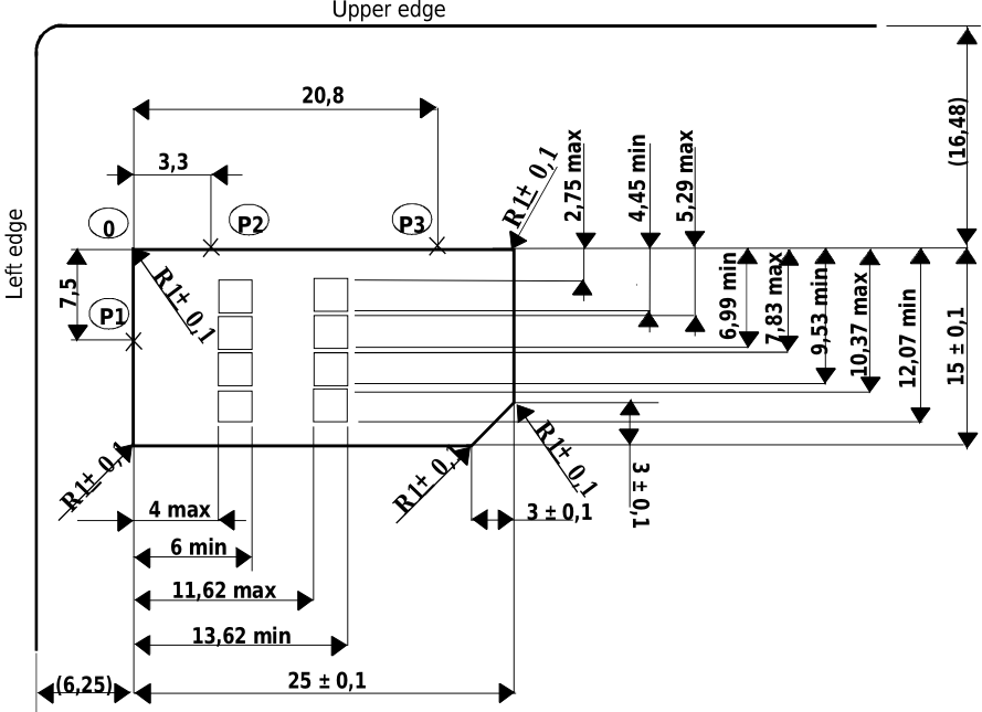
The Plug-in UICC shall have a width of 25 mm, a height of 15 mm, a thickness the same as an ID-1 UICC and a feature for orientation.
Annex A of ISO/IEC 7816-2 [10] applies with the location of the reference points adapted to the smaller size. The three reference points P1, P2 and P3 measure 7,5 mm, 3,3 mm and 20,8 mm, respectively, from 0. The values in figure 2 of ISO/IEC 7816-2 [10] are replaced by the corresponding values of figure 4.1.
The physical characteristics of the Plug-in UICC (Plug-in card) are defined in the present document.
4.0.3 Mini-UICC
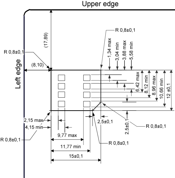
The Mini-UICC shall have a width of 15 mm, a height of 12 mm, a thickness the same as an ID-1 UICC and a feature for orientation.
Annex A of ISO/IEC 7816-2 [10] applies with the location of the reference points adapted to the smaller size below figure 4.2. The values in figure 2 of ISO/IEC 7816-2 [10] are replaced by the corresponding values of figure 4.2.
The physical characteristics of the Mini-UICC are defined in the present document.
4.0.4 4FF
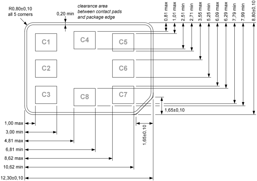
The 4FF shall have a width of 12,3 mm ± 0,1 mm and a height of 8,8 mm ± 0,1 mm, with a thickness range of 0,67 mm + 0,03 mm/-0,07 mm.
Annex A of ISO/IEC 7816-2 [10] applies with the location of the reference points adapted to the smaller size defined below in figure 4.3. The values in figure 2 of the ISO/IEC 7816-2 [10] are replaced by the corresponding values of figure 4.3.
Optionally, the 4FF may be supplied within a card whose width and length are compliant with the ID-1 UICC dimensions but thickness compliant with 4FF. In that case, the 4FF shall be located from 18,22 mm from the top edge of the card and 9,25 mm from the left edge of the card.
The physical characteristics of 4FF are defined in the present document.
The 4FF shall comply with all the characteristics in ISO/IEC 7816-1 [9], except for bending and torsion properties, which apply only to the ID1 form factor. The definition of bending and torsion properties for the 4FF is FFS.
4.1 ID-1 UICC
The contents of this clause have been moved to clause 4.0.1.
4.2 Plug-in UICC
The contents of this clause have been moved to clause 4.0.2.
4.3 Mini-UICC
The contents of this clause have been moved to clause 4.0.3.
4.4 Environmental conditions for card operation and storage
4.4.0 Standard UICC environmental conditions
The standard temperature range for storage and full operational use shall be between -25 °C and +85 °C.
4.4.1 Specific UICC environmental conditions
4.4.1.0 Specific UICC environmental conditions indication
The support of specific UICC environmental conditions is optional for the UICC.
It is up to an application specification to specify the required specific environmental conditions to be supported by the UICC. If an application specification does not specify particular specific UICC environmental conditions then the UICC supports the standard environmental conditions for card operation and storage, as specified in the present document.
If the UICC supports specific environmental conditions, the indication mechanism, as specified in the present document, shall be supported.
4.4.1.1 Temperature range for specific UICC environmental conditions
The support of an extended temperature range is optional for the UICC.
The temperature ranges for full operational use and storage for specific UICC environmental conditions are defined in table 4.1.
| Temperature class | Range |
|---|---|
| A | -40 °C to +85 °C ambient temperature range |
| B | -40 °C to +105 °C ambient temperature range |
| C | -40 °C to +125 °C ambient temperature range |
4.4.1.2 High humidity
The support of the extended humidity condition is optional for the UICC.
A UICC supporting high humidity shall withstand the test conditions as described within JEDEC JESD22-A101D.01 [23] with 1 000 hour duration.
4.5 Contacts
4.5.1 Provision of contacts
4.5.1.1 Terminal
Contacting elements in the terminal in positions C4 and C8 are optional. If present and not used, they shall either be pulled to state L or present a high impedance to the UICC. If it is determined that the UICC is a multi-application UICC, or if the terminal supports optional interfaces using these contacts, then these contacts may be used.
Contact C6 need not be provided for Plug-in/Mini-UICC/4FF cards or any card if the terminal does not support class A operating conditions (see ISO/IEC 7816-3 [11]). Contact C6 shall be provided if the terminal supports the optional interface defined in ETSI TS 102 613 [19].
If present and not used by an optional interface, C6 shall present a high impedance to the UICC or be connected to Gnd.
4.5.1.2 UICC
Contacts C4 and C8 need not be provided by the UICC. If provided, they shall not be connected internally in the UICC if the UICC only contains a Telecom application and is not using these contacts for an additional interface. For 4FF, these contacts may alternatively be connected to Gnd if the UICC is not using them for an additional interface.
Contact C6 shall not be bonded in the UICC for any function other than supplying Vpp or when the UICC supports the optional interface defined in ETSI TS 102 613 [19].
4.5.2 Contact activation and deactivation
4.5.2.1 Contacts assigned by the present document
When using the interface defined in the present document, the terminal shall connect, activate and deactivate the UICC through the contacts C1, C2, C3, C5, C7, in accordance with the operating procedures specified in ISO/IEC 7816-3 [11].
The terminal may switch on and off the clock on contact CLK while the RST contact remains in state L.
For any voltage level, monitored during the activation sequence, or during the deactivation sequence following normal power-down, the order of the contact activation/deactivation shall be respected.
It is recommended that whenever possible, the deactivation sequence defined in ISO/IEC 7816-3 [11] should be followed by the terminal on all occasions when the terminal is powered down.
If the UICC clock is already stopped and is not restarted, the terminal may deactivate all the contacts in any order, provided that all signals reach low level before Vcc leaves high level. If the UICC clock is already stopped and is restarted before the deactivation sequence, then the deactivation sequence specified in ISO/IEC 7816-3 [11] shall be followed.
When Vpp is connected to Vcc, as allowed in the present document for terminals supporting class A operation conditions only, then Vpp shall be activated and deactivated with Vcc, at the time of the Vcc activation/deactivation, as specified in the sequences of ISO/IEC 7816-3 [11].
4.5.2.2 Optional contacts
The use of contacts C4 and C8 for the Inter-Chip USB interface is specified in ETSI TS 102 600 [18].
The use of contact C6 for the UICC-CLF interface is specified in ETSI TS 102 613 [19].
4.5.3 Inactive contacts
The voltages on contacts C1, C2, C3, C6 and C7 of the terminal shall be in the range 0 V ± 0,4 V referenced to ground (C5) when the terminal is switched off with the power source connected to the terminal and when the optional interface defined in ETSI TS 102 613 [19] is not used. The measurement equipment shall have a resistance of 50 kΩ when measuring the voltage on C2, C3, C6 and C7. The resistance shall be 10 kΩ when measuring the voltage on C1.
4.5.4 Contact pressure
The contact pressure shall be large enough to ensure reliable and continuous contact (e.g. to overcome oxidization and to prevent interruption caused by vibration). The radius of any curvature of the contacting elements shall be greater than or equal to 0,8 mm over the contact area.
Under no circumstances shall the contact force exceed 0,5 N per contact.
Care shall be taken to avoid undue point pressure to the area of the UICC opposite to the contact area. Such pressure is potentially damaging to the components within the UICC.
5 Electrical specifications of the UICC - Terminal interface
5.0a Introduction
The provisions of clause 5 apply to the LSE base.
5.0 General requirements
The electrical specification in the present document covers the supply voltage range from 4,5 V to 5,5 V, 2,7 V to 3,3 V, 1,62 V to 1,98 V and 1,1 V to 1,3 V. For each state (V OH , V IH , V IL and V OL ), a positive current is defined as flowing out of the entity (terminal or UICC) in that state. Vpp shall be supported by terminals or UICCs that support the class A operating conditions only.
There are two states for the UICC while the power supply is on:
- the UICC is in operating state when it executes a command from any of its interfaces. This state also includes transmission of the command from the terminal, executing the command and sending the response back to the terminal;
- the UICC is in idle state at any other time. It shall retain all pertinent data during this state. In idle state, the clock may be stopped according to clause 6.6.
The clock duty cycle shall be between 40 % and 60 % of the period during stable operation. A clock cycle is defined at 50 % of Vcc from rising to rising edge or falling to falling edge. When switching clock frequencies terminals shall ensure that no pulse is shorter than 80 ns which is 40 % of the shortest allowed period.
When low impedance drivers are implemented on the I/O line, the I/O electrical circuit design shall insure that potential contention on the line will not result in any permanent damage of the terminal or the UICC. The terminal shall reduce the short circuit current on the I/O line by the means of a series resistor, the value shall be in the range of 47 Ω to 100 Ω.
5.1 Class A operating conditions
5.1.1 Supply voltage Vcc (contact C1)
The terminal shall operate the UICC within the following limits.
| Symbol | Minimum | Maximum | Unit |
|---|---|---|---|
| Vcc | 4,5 | 5,5 | V |
The current consumption of the UICC shall not exceed the value specified in clauses 6.2.2 and 6.2.3 during the ATR (including activation and deactivation).
When the UICC is in idle state (see below) the current consumption of the card shall not exceed 200 µA at 1 MHz and 25 °C. If clock stop mode is enabled, then the current consumption shall also not exceed 200 µA while the clock is stopped.
The terminal shall source the maximum current requirements defined above. It shall also be able to counteract spikes in the current consumption of the card up to a maximum charge of 40 nAs and an amplitude of at most 200 mA, ensuring that the supply voltage stays in the specified range.
NOTE: A possible solution would be to place a capacitor (e.g. 100 nF, ceramic) as close as possible to the contacting elements.
5.1.2 Reset (RST) (contact C2)
The terminal shall operate the UICC within the following limits.
| Symbol | Conditions | Minimum | Maximum | Unit |
|---|---|---|---|---|
| V OH | I OHmax = +20 µA | Vcc - 0,7 | Vcc (see note) | V |
| V OL | I OLmax = -200 µA | 0 (see note) | 0,6 | V |
| t R t F | C out = C in = 30 pF | 400 | µs | |
| NOTE: | To allow for overshoot, the voltage on RST shall remain between -0,3 V and Vcc + 0,3 V during dynamic operation. | |||
5.1.3 Programming voltage Vpp (contact C6)
The UICC shall not require any programming voltage on Vpp. The terminal need not provide contact C6. If the terminal provides contact C6, then, in the case the terminal supports an ID-1 UICC under class A operating conditions only, the same voltage shall be supplied on Vpp as on Vcc, while in the case of Plug-in UICC/Mini-UICC/4FF the terminal need not provide any voltage on C6. Contact C6 may be connected to Vcc in any terminal supporting only class A operating conditions but shall not be connected to ground.
5.1.4 Clock CLK (contact C3)
The terminal shall support 1 MHz to 5 MHz. The terminal shall supply the clock. When only the interface specified in the present document is activated, no "internal clock" shall be used in the UICC.
The duty cycle shall be between 40 % and 60 % of the period during stable operation.
The terminal shall operate the UICC within the following limits.
| Symbol | Conditions | Minimum | Maximum | Unit | |
|---|---|---|---|---|---|
| V OH | I OHmax = +20 µA | 0,7 x Vcc | Vcc (see note) | V | |
| V OL | I OLmax = -200 µA | 0 (see note) | 0,5 | V | |
| t R t F | C out = C in = 30 pF | 9 % of period with a maximum of 0,5 µs | |||
| NOTE: | To allow for overshoot the voltage on CLK shall remain between -0,3 V and Vcc + 0,3 V during dynamic operation. | ||||
5.1.5 I/O (contact C7)
Table 5.4 defines the electrical characteristics of the I/O (contact C7). The values given in the table allow the derivation of the values of the pull-up resistor in the terminal and the impedance of the drivers and receivers in the terminal and UICC.
| Symbol | Conditions | Minimum | Maximum | Unit |
|---|---|---|---|---|
| V IH | I IHmax = ±20 µA (see note 2) | 0,7 x Vcc | Vcc + 0,3 | V |
| V IL | I ILmax = +1 mA | -0,3 | 0,15 x Vcc | V |
| V OH (see note 1) | I OHmax = +20 µA | 3,8 | Vcc (see note 3) | V |
| V OL | I OLmax = -1 mA | 0 (see note 3) | 0,4 | V |
| t R t F | C out = C in = 30 pF | 1 | µs | |
| 100 (see note 4) | ns |
NOTE 1: It is assumed that a pull-up resistor is used in the interface device (recommended value: 20 kΩ).
NOTE 2: During static conditions (idle state) only the positive value can apply. Under dynamic operating conditions (transmission) short-term voltage spikes on the I/O line may cause a current reversal.
NOTE 3: To allow for overshoot the voltage on I/O shall remain between -0,3 V and Vcc + 0,3 V during dynamic operation.
NOTE 4: This value applies when the low impedance buffer is selected.
5.2 Class B operating conditions
5.2.1 Supply voltage Vcc (contact C1)
The terminal shall operate the UICC within the following limits.
| Symbol | Minimum | Maximum | Unit |
|---|---|---|---|
| Vcc | 2,7 | 3,3 | V |
When the UICC is in idle state, the current consumption shall not exceed 200 µA at 1 MHz at +25 °C. When the UICC is in clock stop mode and no other interface is active, the current consumption shall not exceed the following limit:
- UICCs indicating that they require an increased idle current in clock-stop-mode by "UICC increased idle current": 200 µA at +25 °C.
- Other UICCs: 100 µA at +25 °C.
The terminal shall be capable of sourcing the maximum current as defined in table 6.4. It shall also be able to counteract spikes in the current consumption of the card up to a maximum charge of 12 nAs with and an amplitude of at most 60 mA, ensuring that the supply voltage stays in the specified range.
5.2.2 Reset (RST) (contact C2)
The terminal shall operate the UICC within the following limits.
| Symbol | Conditions | Minimum | Maximum | Unit |
|---|---|---|---|---|
| V OH | I OHmax = +20 µA | 0,8 x Vcc | Vcc (see note) | V |
| V OL | I OLmax = -200 µA | 0 (see note) | 0,2 x Vcc | V |
| t R t F | C in = C out = 30 pF | 400 | µs | |
| NOTE: | To allow for overshoot the voltage on RST should remain between -0,3 V and Vcc + 0,3 V during dynamic operations. | |||
5.2.3 Clock CLK (contact C3)
The terminal shall support 1 MHz to 5 MHz. The terminal shall supply the clock. When only the interface specified in the present document is activated, no "internal clock" shall be used in the UICC.
The duty cycle shall be between 40 % and 60 % of the period during stable operation.
The terminal shall operate the UICC within the following limits.
| Symbol | Conditions | Minimum | Maximum | Unit |
|---|---|---|---|---|
| V OH | I OHmax = +20 µA | 0,7 x Vcc | Vcc (see note) | V |
| V OL | I OLmax = -20 µA | 0 (see note) | 0,2 x Vcc | V |
| t R t F | C in = C out = 30 pF | 50 | ns | |
| NOTE: | To allow for overshoot the voltage on CLK should remain between -0,3 V and Vcc + 0,3 V during dynamic operations. | |||
5.2.4 I/O (contact C7)
Table 5.8 defines the electrical characteristics of the I/O (contact C7). The values given in the table allow the derivation of the values of the pull-up resistor in the terminal and the impedance of the drivers and receivers in the terminal and UICC.
| Symbol | Conditions | Minimum | Maximum | Unit |
|---|---|---|---|---|
| V IH | I IHmax = ±20 µA (see note 2) | 0,7 x Vcc | Vcc + 0,3 | V |
| V IL | I ILmax = +1 mA | -0,3 | 0,2 x Vcc | V |
| V OH (see note 1) | I OHmax = +20 µA | 0,7 x Vcc | Vcc (see note 3) | V |
| V OL | I OLmax = -1 mA | 0 (see note 3) | 0,4 | V |
| t R t F | C in = C out = 30 pF | 1 | µs | |
| 100 (see note 4) | ns |
NOTE 1: It is assumed that a pull-up resistor is used on the interface device (recommended value: 20 kΩ).
NOTE 2: During static conditions (idle state) only the positive value can apply. Under dynamic operating conditions (transmissions) short-term voltage spikes on the I/O line may cause a current reversal.
NOTE 3: To allow for overshoot the voltage on I/O shall remain between -0,3 V and Vcc + 0,3 V during dynamic operation.
NOTE 4: This value applies when the low impedance buffer is selected.
5.3 Class C operating conditions
5.3.1 Supply voltage Vcc (contact C1)
The terminal shall operate the UICC within the following limits.
| Symbol | Minimum | Maximum | Unit |
|---|---|---|---|
| Vcc | 1,62 | 1,98 | V |
When the UICC is in idle state, the current consumption shall not exceed 200 µA at 1 MHz at +25 °C. When the UICC is in clock stop mode and no other interface is active, the current consumption shall not exceed the following limit:
- UICCs indicating that they require an increased idle current in clock-stop-mode by "UICC increased idle current": 200 µA at +25 °C.
- Other UICCs: 100 µA at +25 °C.
The terminal shall be capable of sourcing the maximum current as defined in table 6.4. It shall also be able to counteract spikes in the current consumption of the card up to a maximum charge of 12 nAs with an amplitude of at most 60 mA, ensuring that the supply voltage stays in the specified range.
5.3.2 Reset (RST) (contact C2)
The terminal shall operate the UICC within the following limits.
| Symbol | Conditions | Minimum | Maximum | Unit |
|---|---|---|---|---|
| V OH | I OHmax = +20 µA | 0,8 x Vcc | Vcc (see note) | V |
| V OL | I OLmax = -200 µA | 0 (see note) | 0,2 x Vcc | V |
| t R t F | C in = C out = 30 pF | 400 | µs | |
| NOTE: | To allow for overshoot the voltage on RST should remain between -0,3 V and Vcc + 0,3 V during dynamic operations. | |||
5.3.3 Clock CLK (contact C3)
The terminal shall support 1 MHz to 5 MHz. The terminal shall supply the clock. When only the interface specified in the present document is activated, no "internal clock" shall be used in the UICC.
The duty cycle shall be between 40 % and 60 % of the period during stable operation.
The terminal shall operate the UICC within the following limits.
| Symbol | Conditions | Minimum | Maximum | Unit | |
|---|---|---|---|---|---|
| V OH | I OHmax = +20 µA | 0,7 x Vcc | Vcc (see note) | V | |
| V OL | I OLmax = -20 µA | 0 (see note) | 0,2 x Vcc | V | |
| t R t F | C in = C out = 30 pF | 50 | ns | ||
| NOTE: | To allow for overshoot the voltage on CLK should remain between -0,3 V and Vcc + 0,3 V during dynamic operations. | ||||
5.3.4 I/O (contact C7)
Table 5.12 defines the electrical characteristics of the I/O (contact C7). The values given in the table allow the derivation of the values of the pull-up resistor in the terminal and the impedance of the drivers and receivers in the terminal and UICC.
| Symbol | Conditions | Minimum | Maximum | Unit |
|---|---|---|---|---|
| V IH | I IHmax = ±20 µA (see note 2) | 0,7 x Vcc | Vcc + 0,3 | V |
| V IL | I ILmax = +1 mA | -0,3 | 0,2 x Vcc | V |
| V OH (see note 1) | I OHmax = +20 µA | 0,7 x Vcc | Vcc (see note 3) | V |
| V OL | I OLmax = -1 mA | 0 (see note 3) | 0,3 | V |
| t R t F | C in = C out = 30 pF | 1 | µs | |
| 100 (see note 4) | ns |
NOTE 1: It is assumed that a pull-up resistor is used on the interface device (recommended value: 20 kΩ).
NOTE 2: During static conditions (idle state) only the positive value can apply. Under dynamic operating conditions (transmissions) short-term voltage spikes on the I/O line may cause a current reversal.
NOTE 3: To allow for overshoot the voltage on I/O shall remain between -0,3 V and Vcc + 0,3 V during dynamic operation.
NOTE 4: This value applies when the low impedance buffer is selected.
5.4 Class D operating conditions
5.4.0 General
Class D does not apply to removable UICCs.
5.4.1 Supply voltage Vcc (contact C1)
The terminal shall operate the UICC within the following limits.
| Symbol | Minimum | Maximum | Unit |
|---|---|---|---|
| Vcc | 1,1 | 1,3 | V |
When the UICC is in idle state, the current consumption shall not exceed 200 µA at 1 MHz at +25 °C.
The terminal shall be capable of sourcing the maximum current as defined in table 6.4. It shall also be able to counteract spikes in the current consumption of the card up to a maximum charge of 12 nAs with an amplitude of at most 60 mA, ensuring that the supply voltage stays in the specified range.
5.4.2 Reset (RST) (contact C2)
The terminal shall operate the UICC within the following limits.
| Symbol | Conditions | Minimum | Maximum | Unit | |
|---|---|---|---|---|---|
| V OH | I OHmax = +20 µA | 0,8 x Vcc | Vcc (see note) | V | |
| V OL | I OLmax = -200 µA | 0 (see note) | 0,2 x Vcc | V | |
| t R t F | C in = C out = 30 pF | 400 | µs | ||
| NOTE: | To allow for overshoot the voltage on RST should remain between -0,3 V and Vcc + 0,3 V during dynamic operations. | ||||
5.4.3 Clock CLK (contact C3)
The terminal shall support 1 MHz to 5 MHz. The terminal shall supply the clock. When only the interface specified in the present document is activated, no "internal clock" shall be used in the UICC.
The duty cycle shall be between 40 % and 60 % of the period during stable operation.
The terminal shall operate the UICC within the following limits.
| Symbol | Conditions | Minimum | Maximum | Unit | |
|---|---|---|---|---|---|
| V OH | I OHmax = +20 µA | 0,7 x Vcc | Vcc (see note) | V | |
| V OL | I OLmax = -20 µA | 0 (see note) | 0,2 x Vcc | V | |
| t R t F | C in = C out = 30 pF | 50 | ns | ||
| NOTE: | To allow for overshoot the voltage on CLK should remain between -0,3 V and Vcc + 0,3 V during dynamic operations. | ||||
5.4.4 I/O (contact C7)
Table 5.16 defines the electrical characteristics of the I/O (contact C7). The values given in the table allow the derivation of the values of the pull-up resistor in the terminal and the impedance of the drivers and receivers in the terminal and UICC.
| Symbol | Conditions | Minimum | Maximum | Unit |
|---|---|---|---|---|
| V IH | I IHmax = ±20 µA (see note 2) | 0,7 x Vcc | Vcc + 0,3 | V |
| V IL | I ILmax = +1 mA | -0,3 | 0,2 x Vcc | V |
| V OH (see note 1) | I OHmax = +20 µA | 0,75 x Vcc | Vcc (see note 3) | V |
| V OL | I OLmax = -1mA | 0 (see note 3) | 0,2 | V |
| t R t F | C in = C out = 30 pF | 1 | µs | |
| 100 (see note 4) | ns |
NOTE 1: It is assumed that a pull-up resistor is used on the interface device (recommended value: 10 kΩ).
NOTE 2: During static conditions (idle state) only the positive value can apply. Under dynamic operating conditions (transmissions) short-term voltage spikes on the I/O line may cause a current reversal.
NOTE 3: To allow for overshoot the voltage on I/O shall remain between -0,3 V and Vcc + 0,3 V during dynamic operation.
NOTE 4: This value applies when the low impedance buffer is selected.
6 Initial communication establishment procedures
6.0 Introduction
The provisions of clause 6 apply to the LSE base.
6.1 UICC activation and deactivation
The terminal shall activate and deactivate the contacts of the UICC according to clause 4.5.2. During activation supply voltage switching, as defined in clause 6.2, shall take place prior to any further activity not related to the supply voltage switching.
6.2 Supply voltage switching
6.2.0 UICC activation voltage
The terminal shall initially activate the UICC with the lowest voltage class available, i.e. the class providing the lowest voltage. If no ATR is received, the UICC shall be deactivated and activated with the next higher class, if supported by the terminal. If an ATR is received at the first applied voltage class, the contents of the ATR shall be analysed by the terminal. If the operating class used by the terminal is not supported by the UICC, then:
- if the terminal supports any of the voltage classes indicated in the ATR, the terminal shall deactivate the UICC and activate it with a supply voltage class indicated by the UICC;
- if the terminal does not support any of the voltage classes indicated in the ATR, the terminal shall not send any APDU to the UICC. The terminal may deactivate the UICC.
If the ATR is corrupted, the terminal shall reset the UICC at least 3 times using the same operating class before rejecting the UICC. In case of 3 consecutive corrupted ATRs, the terminal may activate the UICC with the next higher class. The terminal's behaviour is restricted, and shall only use the next higher voltage class in the retry attempt in this case.
6.2.1 Supply voltage classes
The supply voltage class shall be indicated in the ATR by the UICC (Ta i , i > 2).
| Symbol | Minimum | Maximum | Unit | Class | Encoding (Binary) |
|---|---|---|---|---|---|
| Vcc | 4,5 | 5,5 | V | A | xx xxx1 |
| Vcc | 2,7 | 3,3 | V | B | xx xx1x |
| Vcc | 1,62 | 1,98 | V | C | xx x1xx |
| Vcc | 1,1 | 1,3 | V | D | xx 1xxx |
| Vcc | RFU | RFU | V | E | x1 xxxx |
| NOTE: | Class A, B and C values are according to ISO/IEC 7816-3 [11]. Class D is a further evolution of values specified in ISO/IEC 7816-3 [11]. It is possible to support one class or a range of classes. In the latter case, the support shall be consecutive e.g. AB, BC, CD. A combination like AC or BD is not allowed. | ||||
NOTE: It is expected that ISO/IEC will assign or reserve the bit encoding for Class D.
6.2.2 Power consumption of the UICC during ATR
The maximum power consumption of the UICC during ATR shall not exceed the minimum power supplied by the terminal during a UICC session as defined in clause 6.2.3.
6.2.3 Application related electrical parameters
The power consumption of the UICC after ATR is restricted to the values indicated in table 6.4.
The Terminal shall be able to provide more current if one of the following conditions is met:
- During the power negotiation procedure (as described in clause 14.5.5), a TERMINAL CAPABILITY command is issued by the terminal indicating a higher value for the maximum available power supply of the terminal. In this case the UICC may draw the indicated power until power-down.
- After an application indicating a higher application power consumption is selected by the terminal. An application is considered selected when the access condition is successfully verified. If no access condition is required for the application, the application is considered selected when an application related command is executed within the selected application. Selecting the application and performing a STATUS command is not considered to be the execution of an application command for these purposes. If the application power consumption indicated in the response to the SELECT or STATUS command is higher than the value indicated by the terminal in the TERMINAL CAPABILITY command, the terminal should deselect the application.
- The Inter-Chip USB interface is activated by the terminal.
The terminal retrieves the application power consumption requirements by selecting the application. It then gets back the application power consumption indication in the response of the SELECT command. It may as well issue a STATUS command within the application and get this information in the response of the command.
Table 6.2: Void
| Symbol | Voltage Class | Maximum for Release 12 and higher (see note) | Maximum for pre-Release 12 | Unit |
|---|---|---|---|---|
| Icc | A | 60 | 60 | mA |
| Icc | B | 50 | 50 | mA |
| Icc | C | 60 | 30 | mA |
| Icc | D | 60 | N/A | mA |
| Icc NOTE: | E The maximum power | RFU consumption for Class D applies | RFU from Release 17 | mA onwards. |
Applications may specify their own maximum power consumption values, up to the maximum specified in table 6.3.
If an application does not indicate its consumption, the terminal shall assume the maximum application power consumption is as specified in table 6.4 or within the limit given in the TERMINAL CAPABILITY command.
The minimum power supply that the terminal shall be able to supply to the UICC during application session at maximum clock speed is specified in table 6.4.
| Symbol | Voltage Class | Minimum | Unit |
|---|---|---|---|
| Icc | A | 10 | mA |
| Icc | B | 10 | mA |
| Icc | C | 10 | mA |
| Icc | D | 10 | mA |
| Icc | E | RFU | mA |
6.3 Answer To Reset content
6.3.0 Introduction
The ATR is the first string of bytes sent from the UICC to the terminal after a reset has been performed. The ATR is defined in ISO/IEC 7816-3 [11].
The terminal shall be able to receive interface characters for transmission protocols other than T = 0 and T = 1, historical bytes and a check byte, even if only T = 0 and T = 1 are used by the terminal.
T = 15 global interface parameters shall be returned by the UICC.
NOTE: ATRs are listed in annex D of the present document.
6.3.1 Coding of historical bytes
The historical bytes indicate to the external world how to use the card. The information carried by the historical bytes of the UICC follows ISO/IEC 7816-4 [12].
The category indicator is the first byte sent by the UICC. Its value shall be '80' which means that the historical bytes are coded in COMPACT-TLV data objects.
The first information sent by the card shall be the "card data service" data object. This data object is introduced by tag '31'. The second information sent by the card shall be the "card capabilities" data object. This data object is introduced by tag '73'. The other data objects are optional.
6.3.2 Speed enhancement
The terminal and the UICC shall at least support (F,D) = (512,8) and (512,16) in addition to (372,1), the default values. However, other values may also be supported. If the terminal requests PPS using values other than those above then the PPS procedure shall be initiated accordingly. The value of the transmission factors F and D is given by the UICC in TA 1 of the ATR.
Table 6.5: Void
When Di = 64 is supported, the interface shall meet the additional requirements below, regardless of the operating conditions used.
| Symbol | Conditions | Minimum | Maximum | Unit |
|---|---|---|---|---|
| t R t F | C in = C out = 30 pF | 400 | ns | |
| NOTE: | To support the additional requirement above, the value of the pull-up resistor that is used on the interface device should be about 10 kΩ. | |||
6.3.3 Global Interface bytes
The global interface bytes are present after T = 15 indication in the ATR. The presence of global interface bytes is optional and the presence is indicated in the tD i (i > 1) indicating T = 15. The content and coding of the first tA i (i > 2) after T = 15 is defined in ISO/IEC 7816-3 [11]. The content and coding of the first tB i (i > 2) after T = 15 is defined in the present document.
| b8 | b7 | b6 | b5 | b4 | b3 | b2 | b1 | Meaning |
|---|---|---|---|---|---|---|---|---|
| 0 | 0 | 0 | 0 | 0 | 0 | 0 | 0 | No additional global interface parameters supported |
| 1 | - | - | 1 | - | - | - | - | Low Impedance drivers and protocol available on the I/O line available (see clause 7.2.1) |
| 1 | 1 | - | - | - | - | - | - | Inter-Chip USB UICC-Terminal interface supported as defined in ETSI TS 102 600 [18] |
| 1 | - | 1 | - | - | - | - | - | UICC-CLF interface supported as defined in ETSI TS 102 613 [19] |
| 1 | - | - | - | 1 | - | - | - | Secure Channel supported as defined in ETSI TS 102 484 [20] |
| 1 | - | - | - | 1 | 1 | - | - | Secured APDU - Platform to Platform required as defined in ETSI TS 102 484 [20] |
| 1 | - | - | - | - | - | 1 | - | eUICC-related functions supported as defined in GSMA SGP.22 [33] |
| 1 | 1 | LSIs supported (see clause 7.5) | ||||||
| NOTE: | Any other value is RFU. | |||||||
6.4 PPS procedure
The terminal and the UICC shall support the PPS procedure in order to use transmission parameters other than the default values. The alternative parameters are indicated in the ATR. The interpretation of these parameters is according to ISO/IEC 7816-3 [11] and to the first tB i (i > 2) after T = 15 in the ATR as defined in table 6.7 in clause 6.3.3. For PPS1 the terminal shall select a value within the range indicated by the UICC as defined in ISO/IEC 7816-3 [11] and complemented in clause 6.3.2. For PPS2 the terminal shall select a value in accordance with the indication in the first tB i (i > 2) after T = 15. PPS2 shall only be used if the first tB i (i > 2) after T = 15 is present in the ATR. The coding for PPS2 is identical to that of the first tB i (i > 2) after T = 15. The value selected depends upon the features supported by the terminal. The content of PPS2 is coded the same way as the first tB i (i > 2) after T = 15. A terminal not supporting any of the features indicated in the first tB i (i > 2) after T = 15 need not to support PPS2 in the PPS procedure.
When the terminal does not support or cannot interpret the values indicated by the card in character TA1 of the ATR, it shall initiate at least one PPS procedure indicating in (Fi, Di) the highest speed the terminal supports before issuing PPS using the default values (372,1).
6.5 Reset procedures
6.5.1 Cold reset
Cold reset is the first reset occurring after activation of the contacts. The cold reset is performed according to ISO/IEC 7816-3 [11] and the UICC shall enter the negotiable mode. After a cold reset, the security status shall be reset.
6.5.2 Warm reset
Warm reset is any reset which is not a cold reset. The warm reset is performed according to of ISO/IEC 7816-3 [11] and the UICC shall enter either the negotiable or the specific mode. If the UICC enters the specific mode, it shall present the same protocol and interface parameters (Fi, Di) as in the session prior to the warm reset. The UICC shall respond with an identical ATR after every warm reset issued within the same session regardless of what application was active. After a warm reset, the security status shall be reset.
6.5.3 Reaction to resets
A UICC complying with the present document shall either be a "Type 1 UICC" or a "Type 2 UICC".
Figure 6.1 illustrates how the respective types of a UICC react to the cold or warm reset.
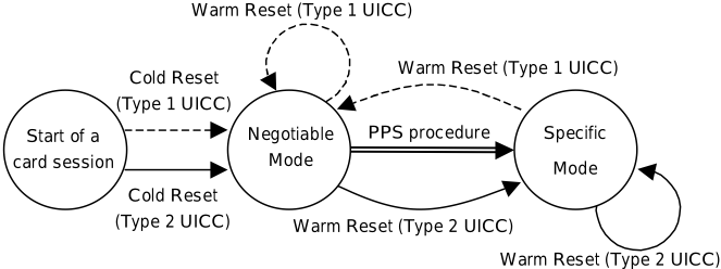
NOTE: See annex I for details.
Figure 6.1: Reaction to resets
6.6 Clock stop mode
The UICC shall support the clock stop procedure as defined in this clause. The clock stop mode is indicated in tA i (i > 2) in T = 15 in the ATR, see ISO/IEC 7816-3 [11]. For a UICC supporting only class A operating conditions, clock stop mode "not allowed" may be indicated, see clause 6.3. If the UICC supports any other operating conditions even together with class A, clock stop mode shall be supported and the indication shall be set accordingly. The terminal shall follow this indication independently of operating conditions indicated by the card.
The terminal shall wait at least 1 860 clock cycles after having received the last character, including the guard time (2 etu), of the response before it switches off the clock (if it is allowed to do so). It shall wait at least 744 clock cycles before it sends the first command after having started the clock.
6.7 Bit/character duration and sampling time
The bit/character duration and sampling time specified in ISO/IEC 7816-3 [11] are valid for all communications.
6.8 Error handling
If mandatory ATR characters (as defined in the present document) are not present in the ATR then it is up to the terminal to decide if a UICC has been activated or not, e.g. it is a card supporting an application not based on the present document.
If, from the terminal point of view, a UICC has been activated and the terminal has received an ATR with protocol errors then the terminal shall perform a Reset. ATR protocol errors are defined as where the ATR has indicated the presence of certain characters but they are not present. If mandatory UICC ATR characters (as specified in the present document) are absent and not indicated to be present then the terminal may consider this from an error handling point of view to be an ATR protocol error. The terminal shall not reject the UICC until at least three consecutive ATRs with protocol errors are received.
During the transmission of the ATR, the error detection and character repetition procedure specified in clause 7.2.2.4, is optional for the terminal. For the subsequent transmission on the basis of T = 0 this procedure is mandatory for the terminal.
For the UICC the error detection and character repetition procedure is mandatory for all communications using T = 0.
6.9 Compatibility
For compatibility with existing terminals, UICCs that are used in applications where the supply voltage class indication is based on the STATUS response procedure (see clause 6.2.3) shall support this procedure in addition to the supply voltage class indication in the ATR as defined in the present document.
In case the UICC does not support any supply voltage indication, the UICC shall be treated as a 5 V only card by the terminal.
7 Transmission protocols
7.0 Introduction
The provisions of clause 7 apply to the LSE base with the following exceptions:
- The provisions of clause 7.4 apply in the context of the related command defined in clause 11.
Clause 7 defines the transmission protocols used to exchange data between the terminal and the UICC. The structure and processing of commands initiated by the terminal for transmission control and for specific control in asynchronous half duplex transmission protocols will be described.
Two different protocols are defined, the character based protocol T = 0 and the block based protocol T = 1.
Both protocols T = 0 and T = 1 are mandatory for the terminal. The UICC shall support either T = 0 or T = 1 or both protocols. The protocols shall be supported as specified in the present document.
The protocol starts after either the answer to reset or a successful PPS exchange. Other parameters provided in the ATR and relevant to a specific protocol are defined in the respective parts of this clause.
The protocol applies a layering principle of the OSI-reference model. Four layers are considered. The layers are:
- the physical layer. The contained definitions are valid for T = 0 and T = 1;
- the data link layer, which consists of:
- a character component;
- a block component;
- block identification;
- send blocks;
- detect transmission and sequence errors;
- handle errors;
- synchronize the protocol;
- the transport layer, which defines the transmission of application-oriented messages specific to each protocol;
- the application layer, which defines the exchange of messages according to an application protocol that is common to both protocols.
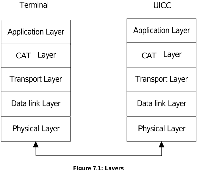
7.1 Physical layer
Both protocols T = 0 and T = 1 shall use the physical layer and character frame as defined in clause 7.2.1.
7.2 Data link layer
7.2.0 Introduction
This clause describes the timing, specific options and error handling for the protocols T = 0 and T = 1.
7.2.1 Character frame
7.2.1.0 Structure, coding and timing
A character that is transmitted over the I/O line is embedded in a character frame.
Before the transmission of a character, the I/O line shall be in state H. Depending upon the convention used, the logical '1' in a character is either represented by state H on the I/O line, direct convention, or state L on the I/O line, inverse convention.
A character consists of 10 consecutive bits (see figure 7.2):
- 1 start bit in state L;
- 8 bits, which comprise the data byte;
- 1 even parity checking bit.
The parity bit is set, in a way, that there is an even number of bits set to '1' including the parity bit in the character frame.
Figure 7.1: Layers
The time origin is fixed as the mean between the last observation of state H and the first observation of state L. The receiver shall confirm the existence of a start bit before 0,7 etu (receiver time). Then the subsequent bits shall be received at intervals of (n + 0,5 ± 0,2) etu (n being the rank of the bit). The start bit is bit 1.
Within a character, the time from the leading edge of the start bit to the trailing edge of the nth bit is (n ± 0,2) etu.
The interval between the leading edges of the start bits of two consecutive characters comprises the character duration (10 ± 0,2) etu, plus a guardtime. Under error free transmission, during the guardtime both the UICC and the terminal shall be in reception mode (I/O line in state H), unless specified otherwise.
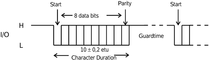
The data shall always be passed over the I/O line with the most significant byte first. The order of bits within a byte (that is, whether the least significant or most significant bit is transferred first) is specified in character TS returned in the answer to reset (see ISO/IEC 7816-3 [11]).
7.2.1.1 Low impedance I/O line behaviour
If the low impedance driver on the I/O line has been selected, as the result of a successful PPS exchange, the following protocol on the I/O line applies.
The transmission state is defined as the period starting from the start bit of the first character to the end of the guardtime of the last character to transmit. During the transmission state the transmitter shall drive the I/O line to the desired level using the low impedance driver, with the exception of the error indication period, e.g. character guardtime of T = 0.
After reception of the last character in a command or response sequence when the communication direction is changed, the entity that is in turn to transmit, terminal or UICC, shall drive the I/O line to the high level using the low impedance driver during the interface inactivity period During clock stop the terminal shall drive the I/O line to high state.
The interface inactivity period ends when the transmission of a new command or its response starts.
7.2.2 Transmission protocol T = 0
7.2.2.0 Introduction
The T = 0 is a half-duplex asynchronous character based transmission protocol.
All commands using the protocol T = 0 are initiated from the terminal by sending a five byte header, which informs the UICC what to do. The terminal will always act as master and the UICC as a slave. The direction of the transmission is assumed to be known to both the UICC and the terminal.
7.2.2.1 Timing and specific options for characters in T = 0
The minimum interval between the leading edge of the start bits of two consecutive characters shall be at least 12 etu.
The maximum interval between the start leading edge of any character sent by the UICC and the start leading edge of the previous character sent either by the UICC or the terminal is the WWT. The value of the WWT shall not exceed 960 × WI × Fi/f. WI is an integer received in the specific interface byte TC2. If no TC2 is available, default value of WI is 10. The clock rate conversion factor, Fi, and the baud rate conversion factor Di, may be indicated in TA1. If TA1 is absent the default values 372 and 1 respectively are used.
If the WWT is exceeded, the terminal shall initiate a deactivation within 960 etu.
7.2.2.2 Command header
A command is always initiated by the terminal which sends an instruction to the UICC in the form of a five byte-header called the command header. The command header comprises five consecutive bytes, CLA, INS, P1, P2 and P3.
These bytes together with any data to be sent with the command form the Command-Transport Protocol Data Unit (C-TPDU) for T = 0. The mapping of the C-APDU onto the C-TPDU is described in clause 7.3.
The terminal transmits the header to the UICC and waits for a procedure byte or a status byte.
7.2.2.3 Command processing
7.2.2.3.0 General description
When the UICC has received the command header, a response containing a procedure byte or a status byte shall be sent to the terminal. Both the terminal and the UICC shall be able to keep track of the direction of the data flow and who has the access to the I/O-line.
7.2.2.3.1 Procedure bytes
The procedure byte indicates to the terminal what action it shall take next.
Procedure bytes are used to keep up the communication between the terminal and the UICC. They shall not be transmitted to the application layer.
The coding of the procedure byte and the action that shall be taken by the terminal is shown in table 7.1.
| Byte | Value | Action |
|---|---|---|
| ACK | Equal to INS byte | All remaining data bytes shall be transferred by the terminal, or the terminal shall be ready to receive all remaining data bytes from the UICC. |
| Equal to complement of INS byte (INS) | The next data byte shall be transferred by the terminal, or the terminal shall be ready to receive the next data byte from the UICC. | |
| NULL | '60' | The NULL-byte requests no further data transfer and the terminal shall only wait for a character conveying a procedure byte. This behaviour provides additional work waiting time as defined in this clause. |
| SW1 | '61' | The terminal shall wait for a second procedure byte then send a GET RESPONSE command header to the UICC with a maximum length of 'XX', where 'XX' is the value of the second procedure byte (SW2). |
| '6C' | The terminal shall wait for a second procedure byte then immediately repeat the previous command header to the UICC using a length of 'XX', where 'XX' is the value of the second procedure byte (SW2). |
After these actions, the terminal shall wait for a further procedure byte or status word.
7.2.2.3.2 Status bytes
The status bytes SW1 SW2 form an end sequence indicating the status of the UICC at the end of a command. A normal ending of a command is indicating by SW1 SW2 = '90 00'.
| Byte | Value | Action |
|---|---|---|
| SW1 | '6X' or '9X' (except '60', '61' and '6C') | The terminal shall wait for a further status word (SW2). The terminal shall return the status words (together with any appropriate data) to the application layer and shall wait for another C-APDU. |
7.2.2.4 Error detection and correction
The error detection and correction procedure is mandatory for T = 0 protocol except for the terminal during the ATR-procedure.
An error, from the receiver's point of view, is defined by an incorrect parity. The error is indicated on the I/O line, which is set to state L at (10,5 ± 0,2) etu after the leading edge of the start bit for the character. The I/O line shall be in state L for a maximum of 2 etu and a minimum of 1 etu. The transmitter shall check the I/O line for parity error indication at (11 ± 0,2) etu starting from the leading edge of the start bit, in the character being transmitted.
If the UICC or terminal as receiver detects a parity error in a character just received, it shall set the I/O line to state L at (10,5 ± 0,2) etu after the leading edge of the start bit for the character for a maximum of 2 etu to indicate the error to the sender (see figure 7.2).
If the transmitter detects an error indication at (11 ± 0,2) etu starting from the leading edge of the start bit, in the character being transmitted, the character shall be sent again after a minimum delay of 2 etu.
7.2.3 Transmission protocol T = 1
7.2.3.0 Introduction
The T = 1 protocol is a half-duplex asynchronous block based transmission protocol. The protocol may be initiated as follows:
- after an ATR due to a cold reset;
- after an ATR due to a warm reset;
- after a successful PPS exchange.
The communication starts with a block sent by the terminal to the UICC. The right to send a block keeps alternating between the terminal and the UICC. A block is the smallest data unit, which can be sent and can contain either application data or transmission control data. A check of the received data might be performed before further processing of the received data.
7.2.3.1 Timing and specific options for blocks sent with T = 1
7.2.3.1.0 Introduction
This clause defines options regarding timing, information field sizes and error detection parameters for blocks sent with T = 1.
7.2.3.1.1 Information field size
The IFSC defines the maximum length of the information field of blocks that can be received by the UICC. The default value of the IFSC is 32 bytes another value may be indicated in the first TA for T = 1 of the ATR.
The IFSD defines the maximum length of the information field of blocks that the terminal can receive. IFSD has a default value of 32 bytes and may be adjusted during the card session. The maximum value of the IFSD is 254 bytes.
7.2.3.1.2 Character waiting integer
CWI is used to calculate CWT and shall be in the range from 0 to 5. The value is set in bits b4 to b1 in the first TB for T = 1 of the ATR.
7.2.3.1.3 Character waiting time
CWT is defined as the maximum delay between the leading edges of two consecutive characters in the block.

The value of CWT may be calculated from the following equation: CWT = (11 + 2 CWI ) etu.
7.2.3.1.4 Block waiting time
BWT is defined as the maximum delay between the leading edge of the last character of the block received by the card and the leading edge of the first character of the next block sent by the card.
- <- Last character of a block sent by the terminal
First character of next block sent by the UICC ->
BWT
Figure 7.4: Block waiting time
BWT is used to detect an unresponsive card.
7.2.3.1.5 Block guard time
BGT is defined as the minimum delay between the leading edge of two consecutive characters sent in opposite directions. The value of BGT shall be 22 etu.

The delay between the last character of a block received by the UICC and the first character of the next block sent from the UICC shall be in the interval:
- BGT < delay < BWT.
7.2.3.1.6 Waiting time extension
WTX is a parameter used to ask for more time to process a command.
7.2.3.1.7 Error detection code
The parameter in the first TC for T = 1 in the ATR is used to define which error detection code to use. LRC shall be used (b1 = 0). All other bits in the first TC for T = 1 of the ATR are RFU and shall be set to 0.
7.2.3.2 Block frame structure
7.2.3.2.0 Overall structure
The protocol consists of blocks, which are transmitted between the terminal and the UICC. Each block has the following structure.
| Prologue field | Information field | Epilogue field | ||
|---|---|---|---|---|
| NAD | PCB | LEN | INF | EDC |
| 1 byte | 1 byte | 1 byte | 0 byte to 254 bytes | 1 byte |
The prologue field and the epilogue field are mandatory. The Information field is optional.
7.2.3.2.1 Prologue field
7.2.3.2.1.0 Field Structure
The prologue field is divided into the following three mandatory fields:
- Node ADdress byte (NAD), 1 byte;
- Protocol Control Byte (PCB), 1 byte;
- LENgth (LEN), 1 byte.
7.2.3.2.1.1 Node address byte
The NAD-byte identifies the source and the intended destination of the block. The NAD may also be used to distinguish between different LSIs if they coexist as well as to provide Vpp state control (bit b8 and b4). Since b8 and b4 are not used, they shall be coded as '0'. Below is the structure of the NAD-byte.
| b8 | b7 | b6 | b5 | b4 | b3 | b2 | b1 |
| Unused | DAD | Unused | SAD |
If multiple LSIs are supported and the terminal and the UICC agreed to use the NAD byte to indicate the LSI, then the LSI is identified by the combination of SAD and DAD values using the encoding in table 7.4a.
| LSI number | Terminal address SAD (terminal to UICC) | UICC address DAD (terminal to UICC) | ||||
|---|---|---|---|---|---|---|
| DAD (UICC to terminal) | SAD (UICC to terminal) | |||||
| b3 | b2 | b1 | b3 | b2 | b1 | |
| '00' | 0 | 0 | 0 | 0 | 0 | 0 |
| '01' | 0 | 0 | 0 | 0 | 0 | 1 |
| ... | ||||||
| '07' | 0 | 0 | 0 | 1 | 1 | 1 |
| '08' | 0 | 0 | 1 | 0 | 0 | 0 |
| RFU | 0 | 0 | 1 | 0 | 0 | 1 |
| '09' | 0 | 0 | 1 | 0 | 1 | 0 |
| ... | ||||||
| '1F' | 1 | 0 | 0 | 0 | 1 | 0 |
NOTE 1: The use of the same value for terminal and UICC addresses is RFU, except for
SAD = DAD = '0'.
NOTE 2: Blocks transmitted from the terminal to the UICC use terminal address as the SAD value and the UICC address as the DAD value. Blocks transmitted from the UICC to the terminal using the same UICC address as the SAD value and the same terminal as the DAD value belong to the same LSI.
If multiple LSI is not supported, only the default value SAD = DAD = 0 shall be supported. All other combinations are RFU.
7.2.3.2.1.2 Protocol Control Byte
All information needed to control the transmission is transferred in the protocol control byte PCB. The coding of the PCB specifies the type of block. In the T = 1 protocol the following three different types of blocks are supported:
- Information block (I-block): which is used to transfer command and response APDUs;
- Receive-ready block (R-block): which is used to transfer acknowledgements;
- Supervisory block (S-block): which is used to send control information.
Tables 7.5 to 7.9 present the coding of the PCB for each block-type, starting with the I-block.
| b8 | b7 | b6 | b5 | b4 | b3 | b2 | b1 |
|---|---|---|---|---|---|---|---|
| 0 | Sequence number, N(S) | Chaining, more-data bit, M | RFU |
| b8 | b7 | b6 | b5 | b4 | b3 | b2 | b1 |
|---|---|---|---|---|---|---|---|
| 1 | 0 | 0 | Sequence number N(R) | See table 7.7 |
| b4 | b3 | b2 | b1 | Value | Meaning |
|---|---|---|---|---|---|
| 0 | 0 | 0 | 0 | '0' | Error free |
| 0 | 0 | 0 | 1 | '1' | EDC and/or parity error |
| 0 | 0 | 1 | 0 | '2' | Other errors |
| X | X | X | X | 'X' | Other values are RFU |
| b8 | b7 | b6 | b5 | b4 | b3 | b2 | b1 |
|---|---|---|---|---|---|---|---|
| 1 | 1 | X | See table 7.9 |
| b5 | b4 | b3 | b2 | b1 | Value | Meaning |
|---|---|---|---|---|---|---|
| 0 | 0 | 0 | 0 | 0 | '0' | Resynchronization |
| 0 | 0 | 0 | 0 | 1 | '1' | Information field |
| 0 | 0 | 0 | 1 | 0 | '2' | Abortion |
| 0 | 0 | 0 | 1 | 1 | '3' | Extension of BWT |
| 0 | 0 | 1 | 0 | 0 | '4' | Error on VPP State (see note) |
| X | X | X | X | X | 'X' | Other values are RFU |
| NOTE: | Not used by UICCs and terminals conforming to the present document. | |||||
The coding of b6 indicates whether it is a request (b6 = 0) or a response (b6 = 1).
7.2.3.2.1.3 Length
The length byte codes the number of bytes in the Information field of the block. The number of bytes in the information field may vary in the range from 0 byte to 254 bytes, depending on the type of block.
The value LEN = '00' indicates that the information field is absent and the value 'FF' is RFU.
7.2.3.2.1.4 Information field
The information field, INF, is optional and it depends on the type of the block what the field will be used for.
| Type of block | INF used for |
|---|---|
| I-block | Transfer command and response APDUs. |
| R-block | Not used. |
| S-block | Transfers non application related information: · INF shall be present (single byte) to adjust IFS with WTX; · INF shall be absent to signal error on VPP, or managing chain abortion or resynchronization. |
7.2.3.2.2 Epilogue field
The epilogue field contains the Error Detection Code-byte (EDC), which transfers the error detection code of the transmitted block.
The LRC as defined in ISO/IEC 7816-3 [11] shall be used.
7.2.3.2.3 Block notations
7.2.3.2.3.1
I-block
The I-blocks are denoted as follows: I(N(S), M) where:
- N(S) is the send-sequence number of the block;
- M is the more-data bit used in the chaining function.
7.2.3.2.3.2 R-block
The R-block is denoted as follows: R(N(R)), where:
- N(R) is the number of the expected I-block.
7.2.3.2.3.3 S-block
S-blocks are always used in pairs. An S(request) is always followed by an S(response) block. The S-blocks are denoted as follows:
- S(RESYNCH request), a request of a resynchronization;
- S(RESYNCH response), an acknowledge of the resynchronization;
- S(IFS request), an offering of a maximum size of the information field;
- S(IFS response), an acknowledge on the information field;
- S(ABORT request), a request to abort the chain function;
- S(ABORT response), an acknowledge of the abortion of the chain function;
- S(WTX request), a request for an extension of the waiting time;
- S(WTX response), an acknowledge of the extension of the waiting time.
7.2.3.3 Error free operation
This clause describes the rules for error free operation with T = 1:
- The first block sent to the UICC shall be either an I-block with N(S) = 0 or an S-block.
- If a sender S sends I(N s (S), 0), the block is acknowledged by the receiver R with an I(N r (S), M). The contents of I(N r (S)) indicate data transfer data and that the receiver is ready to receive the next block from the sender.
- If a sender S sends an I(N s (S), 1) it should be acknowledged by the receiver R with R(N r (R)), where N s (S) ≠ N r (R), to indicate that the received block was correct and that the receiver is ready to receive the next block.
- The UICC might need more than BWT to process the previously received block, an S(WTX request) is sent by the UICC. The terminal shall acknowledge with an S(WTX response). The new allocated time starts at the leading edge of the last character of the S(WTX response).
- To change the value of IFSD, the terminal sends an S(IFS request). The request shall be acknowledged by the UICC with an S(IFS response) with the same INF. The new IFSD is assumed to be valid as long as no new S(IFS request) has been received by the UICC.
- When the receiver has received the number of characters as indicated in the value of the LEN and EDC the receiver returns the right to send.
7.2.3.4 Error handling for T = 1
7.2.3.4.0 General description
This clause contains a description of the rules used to control the error handling for the T = 1 protocol.
The block component of the data link layer shall be able to handle errors like:
- BWT time-out;
- receive an invalid block, i.e. a block with parity errors, EDC error, invalid PCB, invalid length, lost synchronization or failure to receive relevant S(… response) after an S(… request).
Resynchronization of the protocol may be attempted at three consecutive levels. If one level is unsuccessful, then the next level is tried:
- For the terminal, the three levels are:
- Retransmission of blocks.
- Use of S(RESYNCH request).
- Card reset or deactivation.
- For the UICC, the three levels are:
- Retransmission of blocks.
- Use of S(RESYNCH response).
- Without action by the terminal, the UICC becomes unresponsive.
7.2.3.4.1 Protocol initialization
After an ATR due to a Warm reset or successful PPS procedure, the communication between the terminal and the UICC can be initiated. But if the terminal fails to receive an error-free block, in the beginning of the protocol, a maximum of two more successive attempts to receive the block is allowed before resetting or a deactivation of the card takes place.
If the response on the first block sent by the terminal is not sent within BWT, the terminal shall send an R(0).
When the protocol has been initiated and the first block received by the UICC is invalid, the UICC responses with an R(0).
If the terminal fails to receive an error-free block during a card-session, a maximum of two further attempts is allowed before an S(RESYNCH request) is sent.
7.2.3.4.2 Block dependent errors
When an I-block has been sent and a BWT time-out occurs or an invalid block has been received (with the terminal), an R-block is sent, which requests with its N(R) for the expected I-block with N(S) = N(R).
When an R-block was sent and an invalid block is received or BWT time-out, the R-block shall be resent.
When an S(… request) has been sent and either a BWT time-out occurs (with the terminal) or the received response is not an S(… response), the S(… request) shall be resent. But if an S(… response) has been sent and either an invalid block is received or a BWT time-out occurs (with the terminal), an R-block shall be sent. The terminal shall not send an S(IFS request) before the R-block acknowledging a reception of the previous I-block sent by the card.
When the UICC sends an S(IFS request) and receives an invalid block, the S(IFS request) shall be resent maximum one extra time to receive an S(IFS response). After the second failure to receive an S(IFS response), the UICC shall stay in reception mode.
7.2.3.5 Chaining
7.2.3.5.0 Chaining Mechanism
Chaining allows the terminal or the UICC to transfer information, which is longer than IFSC or IFSD. If information longer than IFSC or IFSD is transferred, the information should be divided into pieces, each has a length ≤ IFSC or IFSD. Each piece should be sent in an I-block using the chaining function.
The value of the M-bit in the PCB byte of the I-block controls the chaining function according to:
- M = 0, the block is not chained to the next block;
- M = 1, the block is chained to the next block, which shall be an I-block.
When a receiver receives a more-data I-block, an R(N(R)) shall be sent. N(R) = N(S) of the expected I-block. At least one chained block should follow.
A physical error, e.g. buffer overrun, in the UICC can cause an error in a chaining process. To abort a chain an S(ABORT request) can be sent by either the sender or the receiver. The request shall be answered with an S(ABORT response). When the S(ABORT response) has been received an R-block may be sent to either the terminal or the UICC to give back the right to send to either.
7.2.3.5.1 Rules for chaining
- When the terminal is the receiver, the terminal shall accept a sequence of chained I-blocks sent from the UICC. The length of each block is ≤ IFSD.
- When the UICC is the receiver, the UICC shall accept a sequence of chained I-blocks sent from the terminal. The length of each block shall be equal to the value of IFSC except for the last block whose length can be any value in the range of 0 to IFSC.
- When the terminal is the sender, all I-blocks of a chain shall have LEN = IFSC bytes except for the last, which could have a value in the range of 0 to IFSC.
- When the UICC is the sender, all I-blocks of a chain shall have LEN ≤ IFSD bytes per block.
- When the UICC is the receiver and receives block with LEN > IFSC, the block shall be rejected and acknowledged with an R-block with bits b1 to b4 in the PCB having a value of 2.
For reasons of efficiency, it is not recommended to send empty I-blocks.
7.3 Transport layer
7.3.0 Introduction
This clause describes how the APDU are transported between the terminal and the UICC. For definition of the cases for Data in APDUs see clause 7.4.
7.3.1 Transportation of an APDU using T = 0
7.3.1.0 Introduction
This clause describes the mapping of C-APDUs and R-APDUs for T = 0 protocol, the APDU exchange and the use of the GET RESPONSE command for case 2 and case 4.
7.3.1.1 Mapping of APDUs to TPDUs
7.3.1.1.0 General behaviour
The mapping of the C-APDU onto the T = 0 command header is dependent upon the case of the command. The mapping of the data (if present) and status returned by the UICC onto the R-APDU is dependent upon the length of the data returned.
Procedure bytes '61XX' and '6CXX' are returned by the UICC to control exchanges between the transport layer of the terminal and the UICC, and should never be returned to the application layer of the terminal. Command processing in the UICC is not complete if it has returned procedure bytes '61XX' or '6CXX'.
Normal status on completion of processing a command is indicated if the UICC returns status words '9000' to the transport layer of the terminal. The transport layer of the terminal shall discontinue processing of a command (i.e. pass the R-APDU to the application layer and wait for a further C-APDU from the application layer) on receipt of any status words (but not on receipt of procedure bytes '61xx' and '6Cxx') from the UICC. For case 4 commands only, immediately following successful transmission of command data to the UICC, the transport layer of the terminal shall continue processing the command if warning status bytes ('62xx' or '63xx', with the specific case of '6282' response for SEARCH RECORD command being described in the corresponding section) or application related status bytes ('9xxx' except '9000') are received.
The following descriptions of the mapping of data and status returned by the UICC onto the R-APDU are for information, and apply only after the UICC has completed processing of the command, successfully or otherwise, and all data (if present) has been returned by the UICC under the control of '61XX' and '6CXX' procedure bytes. Detailed use of the INS, , and '60' procedure bytes is not described. INS
The status returned by the UICC shall relate to the most recently received command. Where a GET RESPONSE command is used to complete the processing of a case 2 or case 4 command, any status returned by the UICC after receipt of the GET RESPONSE command shall relate to GET RESPONSE command, not to the case 2 or case 4 command which it completes.
7.3.1.1.1 Case 1
The C-APDU is mapped onto the C-TPDU by assigning the value '00' to the body part (P3 = '00').
| Terminal | UICC | ||
|---|---|---|---|
| Application Layer (C-APDU) | CLA INS P1 P2 | ||
| Transport layer (C-TPDU) | CLA INS P1 P2 P3 = '00' | | Command Processing |
| Transport layer (R-TPDU) | SW1||SW2 | | SW1||SW2 |
| Application Layer (R-APDU) | SW1||SW2 |
The flow of the exchange is as follows:
- The transport layer of the terminal shall send the T = 0 command header to the UICC.
- On receipt of the command header the UICC, under normal or abnormal processing, shall return status to the transport layer of the terminal.
The UICC shall analyse the T = 0 command header to determine whether it is processing a case 1 command or a case 2 command requesting all data up to the maximum length available.
- On receipt of status from the UICC, the transport layer of the terminal shall discontinue processing of the command.
See annex C for details of the exchanges between the transport layer of the terminal and the UICC.
The status words returned to the transport layer of the terminal from the UICC after completion of processing of the command are mapped onto the mandatory trailer of the R-APDU without change.
7.3.1.1.2 Case 2
The C-APDU is mapped onto the C-TPDU without any change.

The flow of the exchange is as follows:
- The transport layer of the terminal shall send the T = 0 command header to the UICC.
- On receipt of the command header the UICC:
- under normal processing shall return data and status to the transport layer of the terminal. The UICC shall use procedure bytes '6Cxx' (and if required, procedure bytes '61xx') to control the return of data (see below); or
- under abnormal processing shall return status only to the transport layer of the terminal.
- On receipt of the data (if present) and status from the UICC, the transport layer of the terminal shall discontinue processing the command.
See annex C for details of the exchanges between the transport layer of the terminal and the UICC, including use of the '61XX' and '6CXX' procedure bytes.
The R-TPDU is mapped onto the R-APDU without any change.
The data (if present) and status returned to the transport layer of the terminal from the UICC after completion of processing of the command are mapped onto the R-APDU as follows:
- The data returned (if present) is mapped onto the conditional body of the R-APDU. If no data is returned, the conditional body of R-APDU is left empty.
- The status returned is mapped onto the mandatory trailer of the R-APDU without change.
7.3.1.1.3 Case 3
The C-APDU is mapped onto the C-TPDU without any change. Lc is a value between 1 and 255.
| Terminal | UICC | ||
|---|---|---|---|
| Application Layer (C-APDU) | CLA INS P1 P2 Lc [Lc bytes of DATA] | ||
| Transport layer (C-TPDU) | CLA INS P1 P2 P3=Lc [Lc bytes of DATA] | | Command Processing |
| Transport layer (R-TPDU) | SW1||SW2 | | SW1||SW2 |
| Application Layer (R-APDU) | SW1||SW2 |
The flow of the exchange is as follows:
- The transport layer of the terminal shall send the T = 0 command header to the UICC.
- On receipt of the command header, if the UICC:
- returns a procedure byte, the transport layer of the terminal shall send the data portion of the conditional body of the C-APDU to the UICC under the control of procedure bytes returned by the UICC; or
- returns status, the transport layer of the terminal shall discontinue processing of the command.
- If processing was not discontinued in step 2(b), the UICC shall return status following receipt of the conditional body of the C-APDU and completion of processing the command.
- On receipt of status from the UICC, the transport layer of the terminal shall discontinue processing the command.
See annex C for details of the exchanges between the transport layer of the terminal and the UICC.
The status words returned to the transport layer of the terminal from the UICC after completion of processing of the command, or the status words returned by the UICC that caused the transport layer of the terminal to discontinue processing of the command, are mapped onto the R-APDU without change.
7.3.1.1.4 Case 4
The C-APDU is mapped onto the C-TPDU by cutting off the last byte (Le) of the body.
| Terminal | UICC | ||
|---|---|---|---|
| Application Layer (C-APDU) | CLA INS P1 P2 Lc [Lc bytes of DATA] Le | ||
| Transport layer (C-TPDU) | CLA INS P1 P2 P3=Lc [Lc bytes of DATA] | | Command Processing |
| SW1||SW2 (61XX, XX = Luicc) | | SW1||SW2 (61XX) | |
| Get Response, P3 = Luicc | | Supply of Response Data | |
| Transport layer (R-TPDU) | Luicc byte of DATA||SW1||SW2 | | Luicc byte of DATA||SW1||SW2 |
| Application Layer (R-APDU) | Luicc byte of DATA||SW1||SW2 |
The flow of the exchange is as follows:
- The transport layer of the terminal shall send the T = 0 command header to the UICC.
- On receipt of the command header, if the UICC:
- returns a procedure byte, the transport layer of the terminal shall send the data portion of the conditional body of the C-APDU to the UICC under the control of procedure bytes returned by the UICC; or
- returns status, the transport layer of the terminal shall discontinue processing of the command.
- If processing was not discontinued in step 2b), following receipt of the conditional body of the C-APDU, the UICC:
- under normal processing, shall return procedure bytes '61xx' to the transport layer of the terminal requesting the transport layer of the terminal to issue a GET RESPONSE command to retrieve the data from the UICC; or
- under abnormal processing, shall return status only to the transport layer of the terminal.
- On receipt of the procedure bytes or status returned in step 3, if the UICC:
- returned '61xx' procedure bytes as in step 3a), the transport layer of the terminal shall send a GET RESPONSE command header to the UICC with P3 set to a value less than or equal to the value contained in the 'xx' byte of '61xx' procedure bytes; or
- returned status as in step 3b) that indicates a warning ('62xx' or '63xx', with the specific case of '6282' response for SEARCH RECORD command being described in the corresponding section), or which is application related ('9xxx' but not '9000'), the transport layer of the terminal shall send a GET RESPONSE command with Le = '00'; or
- returned status as in step 3b) other than that described in step 4b), the transport layer of the terminal shall discontinue processing of the command.
- If processing was not discontinued in step 4c), the GET RESPONSE command shall be processed according to the rules for case 2 commands.
The first R-TPDU from the UICC indicates that the UICC performed the command correct and that the UICC has more data of length Luicc bytes to transfer. The first R-TPDU is mapped without any changes onto the R-APDU.
See annex C for details of the exchanges between the transport layer of the terminal and the UICC, including use of the '61XX' and '6CXX' procedure bytes.
7.3.1.1.5 Use of procedure bytes '61xx' and '6Cxx'
7.3.1.1.5.0 Overall description
The UICC returns procedure bytes '61xx 'and '6Cxx' to the transport layer of the terminal to indicate to it the manner in which it should retrieve the data requested by the command currently being processed. These procedure bytes are only used when processing case 2 and 4 commands using T = 0.
Procedure bytes '61xx' instruct the transport layer of the terminal to issue a GET RESPONSE command to the UICC. P3 of the GET RESPONSE command header is set to 'xx'.
Procedure bytes '6Cxx' instruct the transport layer of the terminal to immediately resend the previous command header setting P3 = 'xx'.
Usage of these procedure bytes during error free processing with case 2 and 4 commands is as defined in clauses 7.3.1.1.5.1 and 7.3.1.1.5.2. In the case of an error, the UICC may return status indicating error or warning conditions instead of the '61xx' or '6Cxx' response.
7.3.1.1.5.1 Case 2 commands
- If the UICC receives a case 2 command header and Le = '00' (with Luicc < 256 bytes) or Le > Luicc, it shall return:
- procedure bytes '6C Luicc' instructing the transport layer of the terminal to immediately resend the command header with P3 = Luicc; or
- status indicating a warning or error condition (but not SW1 SW2 = '90 00').
- If the UICC receives a case 2 command header and Le = '00' (with Luicc = 256 bytes) or Le = Luicc, it shall return:
- data of length Le (= Luicc) under the control of the INS, , or '60' procedure bytes followed by the associated status; or INS
- procedure bytes '61xx' instructing the transport layer of the terminal to issue a GET RESPONSE command with a maximum length of 'xx', 'xx' being less than Luicc (this could happen if the card buffer size is smaller than Luicc); or
- status indicating a warning or error condition (but not SW1 SW2 = '90 00').
- If the UICC receives a case 2 command header and Le < Luicc it shall return:
- data of length Le under the control of the INS, , or '60' procedure bytes followed by procedure bytes '61xx' instructing the transport layer of the terminal to issue a GET RESPONSE command with a maximum length of 'xx'; or INS
- status indicating a warning or error condition (but not SW1 SW2 = '90 00').
7.3.1.1.5.2 Case 4 commands
If the UICC receives a case 4 command, after processing the data sent with the C-APDU, it shall return:
- procedure bytes '61 xx' instructing the transport layer of the terminal to issue a GET RESPONSE command with a maximum length of 'xx'; or
- status indicating a warning or error condition (but not SW1 SW2 = '90 00').
The GET RESPONSE command so issued is then treated as described for case 2 commands.
7.3.2 Transportation of a APDU using T = 1
7.3.2.0 General mechanism
A C-APDU is sent from the application layer of the terminal to the transport layer of the terminal. The transport layer maps the C-APDU onto the INF of an I-block without change. The I-block is sent to the UICC. The Response data (if present) and the status are returned from the UICC to the transport layer of the terminal in the INF of an I-block. If the UICC returns a status which indicates:
- a warning ('62XX' or '63XX');
- an application condition ('9XXX'); or
- a successful execution of the command ('9000');
then it shall also return data (if available) associated with the processing of the command. No data shall be returned with any other status.
The contents of the INF of the I-block are mapped onto the R-APDU without change and returned to the application layer of the terminal. The transportation of APDU messages with T = 1 is mapped to the information of an I-block according to the four different cases described below. Each case is described in detail in clauses 7.3.2.1 to 7.3.2.4.
If the UICC indicates in the ATR both support of LSIs and in the response to MANAGE LSI(configure LSIs) support for LSI selection using the NAD byte, the NAD byte may be used to select the LSI. If the NAD byte is used to select the LSI, the transmission of an APDU (starting with the first I-block of the C-APDU and ending with the last I-block of the R-APDU) on one LSI shall not be interleaved with any block of a different LSI.
NOTE: Interleaving of blocks between different LSIs is FFS.
7.3.2.1 Case 1
C-APDU is mapped to the INF of the I-block without any changes.

| Terminal | UICC | ||
|---|---|---|---|
| Application Layer (C-APDU) | CLA INS P1 P2 | ||
| Transport layer (C-TPDU, INF) | CLA INS P1 P2 | | Command Processing |
| Transport layer (R-TPDU, INF) | SW1||SW2 | | SW1||SW2 |
| Application Layer (R-APDU) | SW1||SW2 |
The response received from the INF in the I-block is mapped unchanged to the R-APDU.
7.3.2.2 Case 2
The C-APDU is mapped to the INF of an I-block without any changes.

The R-APDU consists of either the INF of the I-block or the concatenation of the INF of successive I-blocks all received in the same response, which all shall be chained.
7.3.2.3 Case 3
The C-APDU is mapped without any changes to either an INF or is concatenated onto several successive I-blocks, which all shall be chained.

The INF of the I-block is mapped to the R-APDU without any changes.
7.3.2.4 Case 4
The C-APDU is mapped without any changes to either an INF or is concatenated onto several successive I-blocks, which all shall be chained.

The response consists of either the INF of an I-block received in the response or the concatenation of INF of successive I-blocks in response, which all shall be chained.
7.4 Application layer
7.4.0 Overall description
The application protocol consists of an ordered set of exchanges between the application layer and the transport layer of the terminal. Application protocols are defined in subsequent parts of the present document.
Each step in an application layer exchange consists of a command-response pair, where the application layer of the terminal sends a command to the UICC via the transport layer of the terminal, and the UICC processes it and sends a response to application layer of terminal using the transport layer of the UICC and the transport layer of terminal. Each specific command (C-APDU) has a specific response (R-APDU). The commands and responses are called command messages and response messages. The structure of the C-APDU can be found in clause 10.2. The structure of the R-APDU can be found in clause 10.2.
Both command and response messages may contain data. Thus, four cases shall be managed by the transmission protocols via the transport layer, as shown in table 7.11.
| Case | Command data | Response data |
|---|---|---|
| 1 | Absent | Absent |
| 2 | Absent | Present |
| 3 | Present | Absent |
| 4 | Present | Present |
7.4.1 Exchange of APDUs
Figure 7.14 shows the principle exchange of command/response pairs.
| Terminal | UICC | |
|---|---|---|
| C-APDU | | |
| | R-APDU | |
| C-APDU | | |
| | R-APDU |
7.4.2 CAT layer
7.4.2.0 Overview
The CAT layer uses application status words to indicate:
- the availability of a proactive command for the terminal ('91XX');
- the usage of response data to an envelope command by the terminal (nominal '9000', warning '62XX' or '63XX', checking error '6FXX');
- the temporary unavailability of the CAT to handle an envelope command ('9300'), see clause 14.6.6.
7.4.2.1 Proactive command
Where the status word SW1-SW2 is equal to '9000', the card can reply '91XX' to indicate that a proactive command is pending. The terminal uses the FETCH C-APDU to get the pending proactive command. The terminal sends to the UICC the response of the proactive command execution with the TERMINAL RESPONSE C-APDU.
Even if the command to which the card replied with '91 XX' was sent on a logical channel different from the basic channel, the terminal shall send the FETCH and TERMINAL RESPONSE commands on the basic channel.
The mechanism, described hereafter for a case 4 C-APDU, is independent from the transport protocol.
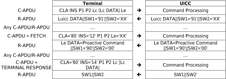
7.4.2.2 ENVELOPE Commands
The ENVELOPE C-APDU is used to transmit data to the CAT as specified in in ETSI TS 102 223 [4]. For some command data, the card may send back response data.
This command is case 3 or 4 and is described hereafter for the different options.
Case 3:
negative acknowledgement

The terminal shall consider the status word received as a negative acknowledgement when the status word present in the R-APDU is '6FXX'.
Case 4: positive acknowledgement

The terminal shall consider the data field received as a positive acknowledgement when the status word present in the R-APDU is '9000'.
Case 4: negative acknowledgement

| Terminal |
|---|
| CLA INS='C2' P1 P2 Lc [Lc DATA] Le=00 |
| Luicc DATA |
| ||SW1='62'or '63'||SW2='XX' |
The terminal shall consider the data field received as a negative acknowledgement when the status word present in the R-APDU is either '62XX' or '63XX'.
7.4.3 Application execution
When a Network Access Application (NAA) is selected on a logical channel, the UICC-Terminal interface should also enable execution of commands for other applications in order to minimize the impacts on service provisioning to the user. Terminals shall set the time-out before terminating a command being processed by the UICC to a value of at least what is specified in table 7.12.
| Case | Time-out |
|---|---|
| The terminal indicates a maximum available power supply in the terminal power supply of TERMINAL CAPABILITY command that is greater than or equal to the UICC Maximum Power Consumption as indicated in EF UMPC . | 20 seconds |
| The terminal is not able to supply the UICC Maximum Power Consumption as indicated in EF UMPC . | T_OP value from EF UMPC |
| UICC Maximum Power Consumption (EF UMPC ) is not present on the UICC. | Not specified |
| UICC |
|---|
| Command Processing |
| Luicc DATA |
| ||SW1='62'or '63'||SW2='XX' |
Application providers are advised to give appropriate warnings to the user before starting an operation that may impact user experience.
7.5 Logical secure element Interfaces
A UICC may support LSIs. If supported by the UICC, this shall be indicated in the ATR.
LSIs provide a multiplexing mechanism which allows the terminal to communicate with multiple LSEs over one physical interface.
LSIs supported by the UICC and the terminal shall be identified by consecutive numbers starting from zero. The maximum value for the LSI is '1F'.
Management of LSIs is done via a dedicated command MANAGE LSI which allows:
- selection of an LSI for subsequent APDUs (mandatory for protocol T = 0, optional for protocol T = 1);
- resetting an LSE without affecting other LSEs; and
- setup of the LSI configuration to be used during the card session.
When the protocol T = 1 is used, the selection of an LSI may be performed using the NAD byte, as defined in clause 7.2.3.2.1.1.
Terminal and UICC shall agree on using LSIs as follows:
- The UICC indicates support for LSIs in the ATR.
- If indicated by the UICC, the terminal shall indicate in PPS2 if LSIs shall be used for the card session.
- If LSIs are used for the card session, LSI 0 is selected after the PPS.
- Before sending a command on an LSI different from 0 or sending any other MANAGE LSI command, the terminal shall perform the setup of the LSI configuration by sending a MANAGE LSI (configure LSIs) APDU to the UICC.
If a terminal uses a non-removable UICC and the LSI configuration to be used is pre-agreed between terminal and UICC (by a mechanism out of scope of the present document), the setup may be skipped.
After the setup, the terminal can use the mechanisms for the management of LSIs.
8 Application and file structure
8.0 Introduction
The provisions of clause 8 apply to the logical UICC with the following exceptions:
- The provisions of clause 8.10 describe the concept of LSEs.
8.1 UICC application structure
An example of organization of applications in the UICC is listed in figure 8.1.
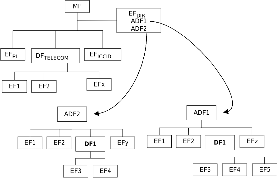
The present document does not impose any restrictions on the location of applications. All applications are uniquely identified by application identifiers that are obtained from EF DIR . These application identifiers are used to select the application.
EF DIR, EF PL , EF ICCID and EF UMPC are all mandatory and reside directly under the Master File. See clause 13 for details.
DF TELECOM is optional. If present it resides under the MF and use the reserved FID '7F 10'. DF TELECOM contains application independent information.
8.2 File types
8.2.0 Introduction
Clause 8.2 defines the file types that apply to applications complying to the present document.
8.2.1 Dedicated files
A Dedicated File (DF) allows for a functional grouping of files. It can be the parent of DFs and/or Efs. DFs are referenced by file identifiers.
An Application DF (ADF) is a particular DF that contains all the DFs and Efs of an application.
8.2.2 Elementary files
8.2.2.1 Transparent EF
An EF with a transparent structure consists of a sequence of bytes. When reading or updating, the sequence of bytes to be acted upon is referenced by a relative address (offset), which indicates the start position (in bytes), and the number of bytes to be read or updated. The first byte of a transparent EF has the relative address '00 00'. The data length is indicated in the SELECT response of the EF.
8.2.2.2 Linear fixed EF
An EF with linear fixed structure consists of a sequence of records all having the same (fixed) length. The first record is record number 1. The length of a record as well as this value multiplied by the number of records are indicated in the SELECT response of the EF.
| Record 1 |
| Record 2 |
| : : |
| Record n |
There are several methods to access records within an EF of this type:
- absolutely using the record number;
- when the record pointer is not set it shall be possible to perform an action on the first or the last record by using the NEXT or PREVIOUS mode;
- when the record pointer is set it shall be possible to perform an action on this record, the next record (unless the record pointer is set to the last record) or the previous record (unless the record pointer is set to the first record);
- by identifying a record using pattern search.
If an action following selection of a record is aborted (e.g. due to an unsuccessful execution of a command), then the record pointer shall remain set at the record at which it was set prior to the action.
It is not possible, at present, to have more than 254 records in a file of this type, and each record cannot be greater than 255 bytes.
8.2.2.3 Cyclic EF
Cyclic files are used for storing records in chronological order. When all records have been used for storage, then the next storage of data shall overwrite the oldest information.
An EF with a cyclic structure consists of a fixed number of records with the same (fixed) length. In this file structure there is a link between the last record (n) and the first record. When the record pointer is set to the last record n, then the next record is record 1. Similarly, when the record pointer is set to record 1, then the previous record is record n. The last updated record containing the newest data is record number 1, and the oldest data is held in record number n.
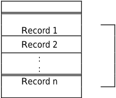
For update operations only PREVIOUS record shall be used. For reading operations, the methods of addressing are Next, Previous, Current and Record Number.
If an action following selection of a record is aborted (e.g. due to an unsuccessful execution of a command), then the record pointer shall remain set at the record at which it was set prior to the action.
It is not possible, at present, to have more than 254 records in a file of this type, and each record cannot be greater than 254 bytes.
8.2.2.4 BER-TLV structure EF
A BER-TLV structure EF is seen at the interface as a set of data objects accessible by commands for handling data objects. The type of data objects in the EF is BER-TLV. A tag can only appear once in an EF.
8.3 File referencing
A File Identifier (FID) is used to address or identify a specific file. The FID consists of two bytes and shall be coded in hexadecimal notation.
FIDs shall be subject to the following conditions:
- the FID shall be assigned at the time of creation of the file concerned;
- no two files under the same parent shall have the same ID;
- the immediate children of the current DF, the parent DF or the immediate children of the parent DF shall not have the same FID.
A path is a concatenation of FIDs. The path starts from MF or the current DF, and ends with the identifier of the file itself. The order of the FIDs is always in the direction from father to child.
A Short File Identifier (SFI) is coded as 5 bits valued in the range from 1 to 30. No two files under the same parent shall have the same SFI.
A DF name is coded on 1 to 16 bytes. The DF name is the AID and shall be unique within a card.
The reserved FID '7FFF' can be used as a FID for the ADF of the current active application on a given logical channel.
8.4 Methods for selecting a file
8.4.0 Default state after UICC activation and ATR
After the UICC activation and the Answer To Reset (ATR), the Master File (MF) is implicitly selected and becomes the current directory. Each file may then be selected by using the SELECT function, using one of the 3 file referencing methods defined in clauses 8.4.1 to 8.4.3.
8.4.1 SELECT by File Identifier referencing
Selecting a DF, an ADF or the MF sets the current directory. After such a selection there is no current EF. Selecting an EF sets the current EF and the current directory remains the DF, ADF or MF, which is the parent of this EF. The current EF is always a child of the current directory. Only the ADF of the current application can be selected by FID.
Any application specific command shall only be operable if it is specific to the Current Directory.
The following files may be selected, by File Identifier (FID) referencing, from the last selected file:
- any file which is an immediate child of the current directory;
- any DF which is an immediate child of the parent of the current DF;
- the parent of the current directory;
- the current DF;
- the ADF of the current active application;
- the MF.
Figure 8.4 is an example of the logical structure for an application conforming to the present document.
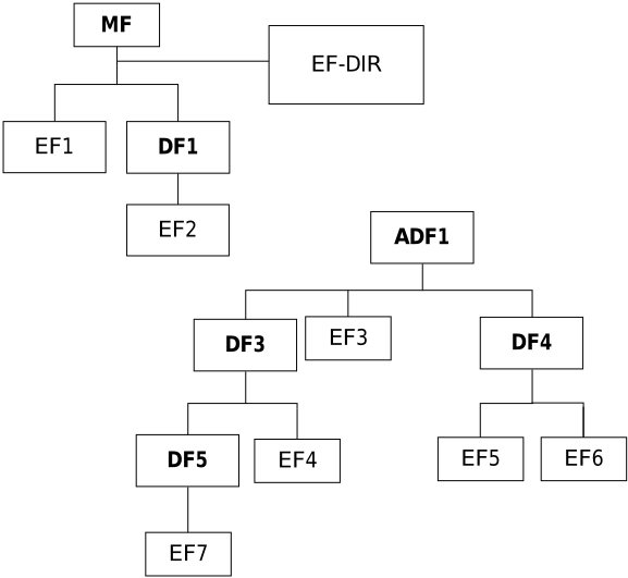
Table 8.1 gives all the valid selections for an application complying to the present document for the logical structure in figure 8.4, if the FID is used. Reselection of the last selected file is also allowed but not shown. In this example, it is considered that the current application (ADF1) has been previously selected by DF name. Therefore ADF1can be selected by using the FID '7FFF'.
| Last selected file | Valid selections |
|---|---|
| MF | ADF1, DF1, EF1, EF-DIR |
| DF1 | MF, ADF1, EF2 |
| ADF1 | MF, DF3, DF4, EF3 |
| DF3 | MF, ADF1, DF4, DF5, EF4 |
| DF4 | MF, ADF1, DF3, EF5, EF6 |
| DF5 | MF, ADF1, DF3, EF7 |
| EF1 | MF, ADF1, DF1, EF-DIR |
| EF2 | MF, ADF1, DF1 |
| EF3 | MF, ADF1, DF3, DF4 |
| EF4 | MF, ADF1, DF3, DF4, DF5 |
| EF5 | MF, ADF1, DF3, DF4, EF6 |
| EF6 | MF, ADF1, DF3, DF4, EF5 |
| EF7 | MF, ADF1, DF3, DF5 |
8.4.2 SELECT by path referencing
A file, DF or EF, may be referenced by path, as defined in clause 8.3. Table 8.2 contains examples of selection by path from figure 8.4. In this example, it is considered that the current application (ADF1) has been previously selected by DF name. The implicit FID of ADF1 '7FFF' is used in table 8.2 (see clause 8.3).
| Last selected DF | Beginning of the path | Example selections |
|---|---|---|
| any | MF | 'EF1', 'EF-DIR', 'DF1', 'DF1||EF2' |
| any | MF | '7FFF||DF3', '7FFF||DF3||EF4', '7FFF||DF3||DF5', '7FFF||DF3||DF5||EF7', '7FFF||DF4', '7FFF ||DF4||EF5', '7FFF||DF4||EF6, '7FFF||EF3' |
| DF1 | Current DF | 'EF2' |
| DF3 | Current DF | 'DF5', 'DF5||EF7', 'EF4' |
| DF4 | Current DF | 'EF5', 'EF6' |
| DF5 | Current DF | 'EF7' |
In the case of "select by path from MF", the terminal may use the special file-id '7FFF' (see clause 8.3) at the beginning of the path. It indicates that the path begins at the ADF of the current active application on this logical channel.
The following restrictions apply:
- In the case of "select by path from MF", the terminal shall not use the file identity of the MF (i.e. '3F00') at the beginning of the path.
- In the case of "select by path from current DF", the terminal shall not use the special file-ID '7FFF' at the beginning of the path.
- In the case of "select by path from MF" or "select by path from current DF", the terminal shall not use the file identity of the current DF.
- In the case of "select by path from MF" or "select by path from current DF", the terminal shall not use an empty data field.
8.4.3 Short File Identifier (SFI)
Any EF within a DF can be implicitly selected without giving a SELECT command by applying one of the following commands at the DF or ADF level and giving a Short File Identifier (SFI) as a part of the command:
- READ BINARY;
- UPDATE BINARY;
- READ RECORD;
- UPDATE RECORD;
- INCREASE;
- SEARCH RECORD;
- RETRIEVE DATA; or
- SET DATA.
Support of SFI for a specific file is indicated if the FCP of the file contains a TLV DO with tag '88'. If the length is 0 it indicates that the file does not support referencing by SFI. If the TLV DO is not present in the FCP it indicates that the 5 least significant bits of the FID are used as SFI.
When the READ RECORD command contains a valid SFI, it sets the file as the current EF and resets the current record pointer. Subsequent records are read with the READ RECORD command without SFI.
When the UPDATE RECORD command contains a valid SFI, it sets the file as the current EF and resets the current record pointer. Subsequent records are updated with the UPDATE RECORD command without SFI.
When the INCREASE command contains a valid SFI, it sets the file as the current EF and resets the current record pointer. Subsequent records are increased with the INCREASE command without SFI.
When the SEARCH RECORD command contains a valid SFI, it sets the file as the current EF and resets the current record pointer. Subsequent records are searched with the SEARCH RECORD command without SFI.
When the RETRIEVE DATA command contains a valid SFI, it sets the file as the current EF and resets the current tag pointer. If segmentation over several APDUs is used to retrieve long structures, subsequent RETRIEVE DATA commands shall be used without SFI.
When the SET DATA command contains a valid SFI, it sets the file as the current EF and resets the current tag pointer. If segmentation over several APDUs is used to set long structures, subsequent SET DATA commands shall be used without SFI.
8.5 Application characteristics
8.5.0 Application selection types
An application may be either explicitly or implicitly referenced.
An application is activated by explicit selecting it with the AID. This sets the application's ADF as the current ADF.
A current ADF can be referenced by FID with the implicit reference value '7FFF'.
8.5.1 Explicit application selection
8.5.1.1 SELECT by DF name
A selectable application, represented in the UICC by the AID, shall be referenced by a DF name coded on 1 byte to 16 bytes. Each name shall be unique within a UICC. A DF name can be used in the SELECT command to select a selectable application.
8.5.1.2 SELECT by partial DF name
A selectable application can also be selected using a partial DF name (when P1 = '04') using the P2 parameters first or only occurrence, next, previous or last as defined in ISO/IEC 7816-4 [12]. In this case, the DF name is right truncated. If several applications starting with the same byte content in the AID are present on the card, the application selected is depending upon the value specified in P2. If the "last" option is indicated in P2, the selected application is the last active application matching the partial DF name, even if it was during a previous card session.
Selection of an application using a partial DF name is optional for mono application cards, but a multi-application card shall support it. The card shall indicate the support of this feature in the "card service data" and the "card capabilities" compact-TLV objects of the ATR historical bytes as specified in ISO/IEC 7816-4 [12].
The interpretation of next, previous and first is to be specified by the application. The application that is selected using these parameters shall match the partial DF name provided in the SELECT command. If the UICC does not support selection with partial DF name, the UICC shall respond with an appropriate response (e.g. command parameters not supported '6A86').
8.5.2 Application session activation
The application session is initiated when the terminal sends a SELECT command, with the application's AID, indicating in the command parameters that the application shall be activated.
An application may need an initialization procedure to be performed after its activation. This procedure is outside the scope of the present document but shall be described in the application specification. The procedure is used to bring the terminal and the application in the UICC to a well-defined state.
After having selected the application the UICC evaluates the security environment for this application. The SE is set according to the verification requirements for the application see table 9.1.
The verification status of the application PIN is updated according to the application's session activation procedure, as specified by the application.
The terminal may send to the UICC a specific STATUS command indicating that the initialization procedure of the application has been successfully executed.
There can only be one active selectable application session on a given logical channel. Therefore, in order to activate a new selectable application session in parallel to another, a new logical channel shall be opened.
A selectable application session may take place on several channel sessions.
8.5.3 Application session termination
An application may have a session termination procedure to be performed before the application is terminated. This procedure shall be described in the application specification. Before this procedure is executed, the terminal may send to the UICC a specific STATUS command indicating that the termination procedure of the application will start. After this termination procedure has been executed the terminal and the application are in a well-defined state.
An application session is then terminated if any of the following events occur on each logical channel that the application session has been activated on:
- Implicitly; if a SELECT by DF name command with an AID different from the currently active application is performed by the UICC, indicating in the command parameters that this new application shall be activated.
- Explicitly; if the application is reselected using the SELECT by DF name command with the AID corresponding to the currently active application, and indicating in the command parameters that the application shall be closed; The current directory, current EF and current application are the same as after the ATR on logical channel zero.
- If the logical channel is closed.
An application session is also terminated when the terminal performs a reset of the UICC.
The verification status of the application PIN is updated according to the application's session termination procedure, as specified by the application.
8.5.4 Application session reset
An application is reset if the application is reselected using the SELECT by DF name command with the AID corresponding to the currently active application, indicating in the command parameters that the application shall be activated.
Reset initializes the application session activation procedure. The security status of the application is updated according to the application's session activation procedure, as specified by the application.
8.5.5 Void
8.6 Reservation of file Ids
The following FIDs are reserved by the present document:
- ADF:
- Operational use (implicit FID for the current ADF):
- '7FFF'.
- Dedicated Files:
- Administrative use:
- '7F4X', '5F1X', '5F2X'.
- Operational use:
- '7F10' (DF TELECOM );
'7F20' (DF GSM );
'7F21' (DF DCS1800 ); and
'7F23' (DF FP-CTS ) are reserved for 3GPP, 3 rd Generation Partnership Project;
- '7F11' (DF CD ) is reserved for assignment in the present document;
- '7F22' (DF IS-41 ) is reserved for ANSI, American National Standards Institute, USA;
- '7F24' (DF TIA/EIA-136' ) is reserved for TIA, Telecommunications Industry Association, USA;
- '7F25' (DF TIA/EIA-95' ) is reserved for 3GPP2, 3 rd Generation Partnership Project 2;
- '7F26' (DF GSMA ) is reserved for GSMA, GSM Association;
- '7F2X', where X ranges from '6' to 'F' are reserved for future assignments.
- For information:
- '7F31' (DF IDEN ) is used in the iDEN specification by Motorola, Inc, USA;
- '7F80' (DF PDC ) is used in the PDC specification by ARIB, Association of Radio Industries and Businesses, Japan;
- '7F90' (DF TETRA ) is used by TETRA Association, Terrestrial Trunked Radio.
If a DF is reserved for an organization, it is responsible for all content inside this DF and requests for allocation of DF or EF identifiers under the DFs shall be made to the responsible organization. The same should be done for DFs used by an organization:
- Elementary files:
- Administrative use:
- '6F XX' in the DFs '7F 4X'; '4F XX' in the DFs '5F 1X', '5F2X';
- '6F 1X' in the DFs '7F 10', '7F 20', '7F 21';
- '4F 1X' in all 2 nd level DFs;
- '2F EX' in the MF '3F 00'; '2F07' EF ENV-CLASSES (specified in ETSI TS 102 671 [27]).
- Operational use:
- '6F 2X', '6F 3X', '6F 4X' in '7F 10' and '7F 2X';
- '4F YX', where Y ranges from '2' to 'F' in all 2 nd level DFs;
- '2F05', '2F06' and '2F 1X' in the MF '3F 00'.
- Operational use ISO/IEC 7816-4 [12]:
- '2F00' EF DIR , '2F01' EF ATR in the MF '3F00'.
In all the above, X ranges, unless otherwise stated, from '0' to 'F'.
8.7 Logical channels
Logical channels are defined in ISO/IEC 7816-4 [12]. The present document supports the first (i.e. CLA byte coded as in table 10.3) and the further (i.e. CLA byte coded as in table 10.4a) interindustry values for the CLA byte as defined in ISO/IEC 7816-4 [12], which support up to 19 logical channels in addition to the basic logical channel 0. Channel 0 is always available and open throughout the card session.
A UICC which supports logical channels indicates it in the ATR, together with the assignment methods and maximum number of logical channels it supports. The UICC supporting logical channels shall support:
- at least one channel in addition to the basic channel; and
- logical channel number assignment by the UICC.
Command interdependencies on one logical channel are independent of command interdependencies on another logical channel.
There is no interleaving of commands and their responses across logical channels; between the receipt of the command APDU and the sending of the response APDU to that command, only one logical channel is active.
In order to be accessed from several logical channels at the same time, a given file (EF, DF, ADF) shall be indicated as "shareable" in its file descriptor.
Applications are responsible for keeping data consistency (in the card and the terminal) when accessing the same file from different logical channels.
NOTE: Special attention should be given to cyclic files, e.g. when the file is read in one channel and updated in another.
A logical channel is opened by using a MANAGE CHANNEL command, in which the card assigns a channel number and returns it in the response.
The logical channel remains open until it is explicitly closed by a MANAGE CHANNEL command, or if the UICC is deactivated.
When the open function is performed from the basic channel, then after a successful open, the MF shall be implicitly selected as the current DF. When the open function is performed from a logical channel which is not the basic one, then after a successful open, the current DF of the logical channel from which the command was issued shall be selected as the current DF. In both cases, no current EF is selected in the new logical channel.
| Parameters of the | Characteristics of the new channel | |
|---|---|---|
| MANAGE CHANNEL command | Current DF | ADF of current active application (referred to by the special '7FFF' file-ID) |
| CLA = 00 (from the basic channel) | MF | Undefined |
| CLA ≠ 00 (from the non-basic channel) | The same current DF as the one where the open channel is performed | ADF the application active in the logical channel where the open channel was performed |
Once a new channel is opened, the current DF and the current EF are independent per each logical channel.
If the MANAGE CHANNEL command is performed on a DF or ADF that is not shareable, the card shall respond with an appropriate error message. The response shall indicate that the command is not allowed. No new channel is opened.
8.8 Shareable versus not-shareable files
A file (EF, DF or ADF) can be accessed (selected, read, updated, deleted, deactivated, activated, increased, searched, etc.) concurrently by different applications:
- by terminal applications through different logical channels;
- by UICC-based applications such as remote file management and toolkit applications.
The outcome of concurrent access is determined by the shareable/not-shareable bit in the file descriptor byte in the FCP of the accessed file as follows:
- If a file is indicated as shareable, then applications may perform authorized operations on the file independently of whether or not the file is the current file of any other application.
- If a file is indicated as not-shareable and is the current file of one application, then another application cannot perform any operation on the file regardless of authorization.
A consequence of the first rule is that if changes to a shareable file are permitted by the file's security conditions, then the file can be changed by one application while it is currently selected and being used by a second application. Descriptions of individual commands include the details of behaviour interaction in the shareable case.
A consequence of the second rule is that an application acquires exclusive access to a not-shareable file by successfully selecting it. Access by any other application, including an attempt to select the file, shall return the status word '6985' (conditions of use not satisfied).
For the purpose of this clause, concurrent access to a file by two executing instances of a single application is considered to be accessed by two different applications.
For shareable files, file access shall be managed independently for each accessing application. In particular, a record-based file and a BER-TLV structure file shall have different pointers for each accessing application.
8.9 Secure channels
Secure channels are defined in ETSI TS 102 484 [20]. There are two types of APDU based secure channel: Application to Application APDU secure channels and Platform to Platform APDU secure channels.
Support of secure channels is optional for the Terminal and the UICC. The support by the UICC is indicated in the ATR.
A secure channel is a special secured version of a logical channel. A secure channel is created by first opening a logical channel, and then securing the channel using the MANAGE SECURE CHANNEL command. Logical channel 0 cannot be a secure channel for application to application secure channel.
A Platform to Platform APDU secure channel shall only be allowed on logical channel 0. Logical channel use shall be allowed within a Platform to Platform secure channel. All commands other than MANAGE SECURE CHANNEL, TRANSACT DATA and GET RESPONSE are secured by using a Platform to Platform secure channel, including proactive commands.
For the application-to-application secure channel, a UICC application shall be selected by one of the following mechanisms:
- a UICC application becomes explicitly selected before the MANAGE SECURE CHANNEL - Establish SA - Master SA command; or
- a UICC application becomes implicitly selected upon successful completion of a MANAGE SECURE CHANNEL - Establish SA - Master SA command.
8.10 Logical secure elements
A UICC may support several LSEs on the same physical element. Each LSE acts and is handled by the terminal like a separate SE. The terminal communicates with the different LSEs via LSIs.
Each LSE operates logically independently from the others. As seen on the interface, each LSE has its own file system, its own applications, its own AIDs, its own independent security status, its own CAT session (which means that several of them can run interleaved in parallel on the different LSIs), and its own runtime environment.
The terminal can switch between the LSEs by sending MANAGE LSI (select LSI) commands or by selecting the LSI via the NAD byte when using T = 1.
The MANAGE LSI command also allows resetting an LSE. Such a reset shall be equivalent to a warm reset of the interface for a UICC not supporting LSEs. A cold reset or a warm reset of the physical interface results in resetting all LSEs.
When the terminal receives a REFRESH proactive command with mode "UICC reset" on an LSI, the terminal shall reset only the corresponding LSE via a MANAGE LSI command.
If the UICC supports the UICC-CLF interface as defined in ETSI TS 102 613 [19], this interface shall be assigned to at most one LSE. The ATRs returned in MANAGE LSI (reset LSE) for the different LSEs shall reflect the support of this interface by the LSE. The assigned LSE may be updated by the terminal using the MANAGE LSI (assign SWP) command. The assigned LSE does not change with a reset of the UICC and is also used for any communication that occurs while the interface defined in the present document is deactivated.
9 Security features
9.0 Introduction
The provisions of clause 9 apply to the logical UICC with the following exceptions:
- The provisions of clause 9.6 describe the specific security features of LSEs.
Every application that conforms to the present document may define security features in addition to the mandatory features defined in this clause.
9.1 Supported security features
A terminal that conforms to the present document and is designed for a multi-application UICC shall recognize the security attribute tags specified in the present document.
A single application terminal conforming to the present document shall support one of the access rules format specified in the present document. The application specifies which format is used.
A multi-application capable terminal that is designed to support a multi-verification capable UICC shall, from the security context point of view, support the usage of the level 1 verification requirements (PIN) and the level 2 verification requirements (PIN2). The coding is defined in table 9.3. The terminal shall, in addition, support the usage of a universal PIN as defined in the present document.
A multi-verification capable UICC conforming to the present document shall, from the security context point of view, support more than one level 1 user verification requirement (PIN). The specific key reference for the level 1 PIN is specified by each application in accordance with table 9.3. In addition, the application may specify a level 2 user verification requirement (PIN2). A multi-verification capable UICC should support the use of a universal PIN. A multi-verification capable UICC shall support access rules defined in security attributes indicated in tag '8B' (i.e. referenced to expanded format).
A single verification capable UICC shall, from the security context point of view, support one level 1 user verification requirement (PIN) as defined in table 9.3. In addition the application may specify a level 2 user verification requirement as a second application verification requirement (PIN2). A single verification capable UICC may contain one or more selectable applications if there are no security aspects to be considered between the different selectable applications. From the security point of view only one level 1 verification requirement (PIN) is assigned to all ADFs/DFs and files on the UICC. In addition, a level 2 user verification requirement (PIN2) may be assigned for each application. From the security and access rules point of view the UICC is seen as a single application card. The coding of the level 1 and level 2 user verification requirement shall be according to table 9.3.
9.2 Security architecture
9.2.0 Overview and basic rules
An application on a UICC conforming to the present document shall specify a level 1 key reference as the user verification (PIN). In addition the application may specify a level 2 key reference as a second user verification requirement (PIN2). The coding of the level 1 and level 2 user verification requirement shall be according to table 9.3. In addition, an application may specify the usage of a universal PIN as a replacement for the application PIN.
In order to perform commands other than SELECT and STATUS/GET RESPONSE, the security condition for the file shall be met. A security condition data object contains the conditions to be met in order to perform certain commands on a selected ADF/DF/EF.
If the UICC cannot determine the access condition for the requested access to a file, then the requested access to this file shall not be granted and the card shall return an error status word '6982' (Security status not satisfied).
The security architecture consists of the following parts:
- Security attributes: a set of access rules.
- Access rules: consist of an access mode and one or more security conditions.
- Access Mode (AM): indicates to which operations (commands) the security condition applies.
- Security Condition (SC): contains references to the applicable key references (PINs).
Clauses 9.2.1 to 9.2.7 define the parts constituting the security architecture.
9.2.1 Security attributes
The security attributes are attached to an ADF/DF/EF and they are part of the FCP. The security attributes are indicated in the FCP using tag '8B', tag '8C' or tag 'AB' depending upon the format used, see ISO/IEC 7816-4 [12].
9.2.2 Access mode
The access mode byte/data object (AM byte/AM_DO) defines for which group/type of command(s) the security condition apply. The interpretation of the AM byte/AM_DO is file dependent (i.e. different for a DF/ADF and an EF), see ISO/IEC 7816-4 [12]. The command type/group is defined and coded according to ISO/IEC 7816-4 [12].
For instructions not belonging to a group as defined in ISO/IEC 7816-4 [12] the access rights can be indicated using AM_DO tags '81' to '8F'. The value of the tag defining the AM_DO indicates what description of the command exists in the definition list to follow in the value part of the data object. The coding of bit b4 to b1 in the AM_DO tag is defined in ISO/IEC 7816-4 [12].
The security conditions for bits not set to '1' in the AM byte are set to NEVer by default.
9.2.3 Security condition
The Security Condition (SC) indicates which security related procedures (user PIN verification) shall be satisfied before a command may be performed on a file. The SC is coded according to ISO/IEC 7816-4 [12].
9.2.4 Access rules
The access rule defines the security conditions for access to a file for each command/command group indicated in the AM-byte/AM_DO. The security condition is indicated in the SC-byte(s)/SC_DO(s) following the AM-byte/AM_DO. The access rule is coded by using one or more AM-bytes/AM_DOs each followed by one or more security conditions that are to be satisfied for the appropriate access.
The access rules may be coded in a compact or an expanded format. Furthermore, it is possible to combine one or more SCs to one AM such that at least one SC (the OR relation) shall be fulfilled before the command can be executed. It is possible to combine the SC such that more than one SC has to be fulfilled (the AND relation).
An access rule is a set of requirement(s) that shall be met in order to perform operations on a file. An access rule contains one or more security attributes, the AM byte/AM_DO in the attribute indicates what commands can be performed and the SC byte/SC_DO indicates what SC shall be met to be able to perform the commands indicated in the AM byte/AM_DO. The content of each AM byte (in compact format) or AM_DO (in expanded format) shall be unique within the same access rule. SC_DOs OR and AND relations shall contain at least two access conditions. The terminal shall ignore an AM/SC combination which is syntactically incorrect or with unknown instructions.
The CRT tags for SC_DOs are defined in ISO/IEC 7816-4 [12]. The SC required to perform commands indicated in the AM byte/AM_DO may be a simple condition or a logical OR or AND condition of several SC_DOs. The constructed TLV object containing AM bytes/AM_DOs and SC bytes/SC_DOs is an access rule. An access rule can be indicated in the FCP in one of the following ways:
- Tag '8C' Security attributes: Compact format.
- Tag 'AB' Security attributes: Expanded format.
- Tag '8B' Security attributes: Referenced to expanded format.
9.2.5 Compact format
The compact format is indicated by tag '8C' in the FCP. In the compact format an access rule consists of an AM byte and one or more SC bytes as defined in ISO/IEC 7816-4 [12].
The AM byte conveys two types of information. The interpretation of the AM byte itself (coded on b8), and the number of SC bytes following, this is equal to the number of bits set to '1' in bits b7 to b1 in the AM byte. If b8 in the AM byte is set to '0' the interpretation of bits b7 to b1 is as defined in ISO/IEC 7816-4 [12]. If b8 in the AM byte is set to '1' the usage of bits b7 to b4 is proprietary.
When multiple sets of an AM byte and one or more corresponding SC bytes are present in the value field they present an OR condition.
EXAMPLE 1: The access rule for READ always for an EF is coded using the compact format as follows.
| Tag | L | AM | SC |
| '8C' | '02' | '01' | '00' |
EXAMPLE 2: The access rule for UPDATE user PIN verification and READ always for an EF is coded using the compact format as follows.
| Tag | L | AM | SC | SC |
| '8C' | '03' | '03' | '10' | '00' |
9.2.6 Expanded format
The expanded format is indicated by tag 'AB' in the FCP. This tag indicates a constructed data object. In the expanded format an access rule consists of one AM_DO followed by a sequence of SC_DOs. The contents of the AM_DO is defined by the tag that it is indicated with, see ISO/IEC 7816-4 [12]. Tag '80' indicates that the AM_DO contains an AM byte. The sequence of SC_DOs following the AM_DO is relevant for all commands specified in the AM_DO. The different SC_DOs can form an OR or an AND condition as defined in ISO/IEC 7816-4 [12]. The information following tag 'AB' in the FCP can contain a lot of data if the rule is complex. This information is part of the FCP that is transmitted over the interface in the response to a SELECT or a STATUS command. The structure of the security attribute in expanded format is as follows.
| Tag | length | AM_DO tag AM_DO | SC_DO tag SC_DO | AM_DO tag AM_DO | SC_DO tag SC_DO |
|---|---|---|---|---|---|
| 'AB' | See ISO/IEC | See ISO/IEC | See ISO/IEC | See ISO/IEC | |
| 7816-4 [12] | 7816-4 [12] | 7816-4 [12] | 7816-4 [12] |
An example using the expanded format coding is given in annex E.
9.2.7 Access rule referencing
Access rules may be shared between files in the UICC by referencing. This is accomplished by storing the security attributes in the expanded format in a linear fixed file, the Access Rule Reference(EF ARR ) in the UICC. The structure of the EF ARR file is as follows.
| Record Number (ARR) | Record Content (Access Rule) |
|---|---|
| '01' | AM_DOSC_DO 1 SC_DO 2 AM_DOSC_DO 3 SC_DO 4 …. |
| '02' | AM_DOSC_DO 1 AM_DOSC_DO 5 SC_DO 6 …. |
The referenced format is indicated in the FCP following tag '8B'. The access rule is stored in a file, EF ARR . This file is a linear fixed file. Referencing is based on the following two methods:
- File ID and record number (File ID, record number).
- File ID, SE ID and record number (File ID, SE ID, record number).
The second possibility allows the usage of different access rules in different security environments. When referencing EF ARR is based on the file ID, the rules for the location of the access rules are as follows:
- For an EF, if the EF(ARR) file with the file ID indicated in tag '8B' cannot be found in the current DF, the parent DF shall be searched for EF(ARR). This process shall continue until the EF(ARR) is found or until an ADF or the MF is reached.
- For a DF, if the EF(ARR) file with the file ID indicated in tag '8B' cannot be found in the parent DF, the grandparent DF shall be searched for EF(ARR). This process shall continue until the EF(ARR) is found or until an ADF or the MF is reached.
- For the MF or an ADF, the EF(ARR) file with the file ID indicated in tag '8B' shall be searched under the MF.
NOTE: There may be several EF ARR containing access rules under the same DF. They are distinguished and referred to by their respective file-Ids.
The structure of the access rule referencing DO is as follows.
| Tag | Length | Value |
|---|---|---|
| '8B' | '03' | File ID, record number |
| '8B' | '02' + n x '02' | File ID, SE Id n1 , Record number X, SE Id n2 , Record number Y, etc. |
Each record in Ef ARR contains a sequence of AM_DOs followed by SC_DOs. The content of the record is the rule that applies for access to the selected file. The content of a sample EF ARR file is given in annex F. The option with the SE ID referencing shall be used in an application where several security environments exist.
9.3 Security environment
9.3.0 Description
The security environment is a mechanism to specify for the card system the security functions that are available to provide protection to commands for a specific application of the card according to ISO/IEC 7816-4 [12]. The security environment for a multi-application UICC is defined as a container for each activated application on the UICC. In case of a single application card the security environment is valid for the whole UICC. In the referenced format it is possible to indicate different access rules as a function of the SE that is in use.
9.3.1 Definition of the security environment
In case the referenced format contains SEID as the referencing method the terminal shall evaluate the SEID and perform the appropriate user verification accordingly.
The following properties are mapped to SE01 and SE00.
| SE ID | Properties |
|---|---|
| '00' | (The global Application PIN is disabled AND the Universal PIN is disabled) OR (The global Application PIN is disabled AND the Universal PIN is enabled and used) |
| '01' | (The global Application PIN is enabled) OR (The global Application PIN is disabled AND the Universal PIN is enabled but not used) |
The above requirements are derived from table 9.1. A multi-application capability UICC that supports the universal PIN shall also support the use of SE00 and SE01 in order to allow application verification requirement to be replaced by the Universal PIN. A multi-application capability terminal shall support SEID referencing in EF ARR .
| Universal PIN status | ||||
|---|---|---|---|---|
| PIN to verify | E | E | NE | |
| APPL_PIN status | APPL_PIN SE01 UUP Universal_PIN | APPL_PIN SE01 NO PIN | ||
| NE | SE00 DUUP NO PIN SE01 | SE00 NO PIN SE00 | ||
| Key: | UUP: DUUP: | Use Universal PIN (usage qualifier set to '08'). Do not Use Universal PIN (usage qualifier set to '00'). | ||
| E: | Enabled | |||
| NE: | Not Enabled | |||
The Security Environment when no application is active on a given logical channel (SE_No_Active_Application) is set as follows: all application PINs assigned on the UICC are considered as APPL_PIN; if at least one of the application PINs is disabled, the SE is SE#00 except for the case where the Universal PIN is enabled but the default usage qualifier (see clause 9.5.2) is set to "do not use" as defined in table 9.1 (DUUP). This Security Environment is valid under the MF and under its child DFs/EFs as long as no application is active.
The Security Environment when an application is active on a given logical channel (SE_Active_Application) is determined as in table 9.1 with the APPL_PIN being the Application PIN of the active application. This Security Environment is valid under the ADF/MF and their child DFs/Efs.
9.3.2 Logical Channels and Security Environment
A UICC supporting logical channels has the security environment set during the application activation and is valid for the logical channel on which the application is activated. The security environment remains the same on this logical channel until a new application is selected or the status of the PIN status DO has changed, i.e. the application or universal PIN status has been changed from disabled to enabled or vice versa.
The security environment of an application running on a logical channel is inherited when a new channel is opened from the non-basic channel. It is evaluated as after the ATR and set as the SE_No_Active_Application when the new channel is opened from the basic channel.
Any command issued on a logical channel affecting the SE setting only affects the SE on the channel where the command was issued and other channels with inherited security from this channel. The SE change on a channel with inherited security also changes the SE on the channel from which the security status was inherited.
9.4 PIN definitions
9.4.0 Introduction
Clause 9.4 defines the types of PIN that shall exist on a UICC, namely the Universal PIN and the application PIN, as well as other types of access conditions needed by the UICC/an application.
9.4.1 Universal PIN
A Universal PIN is a PIN that is used in a multi-application environment to allow several applications to share one common PIN. The Universal PIN is a global access condition that has been assigned a key reference value '11'. This key reference value shall not be used for anything else but to indicate the Universal PIN.
In order to give access to several applications on a multi-application UICC, a terminal conforming to the present document shall support the usage of the Universal PIN. A multi-application UICC according to the present document should support the usage of a Universal PIN.
If an application allows the use of the Universal PIN as replacement PIN, the Universal PIN shall be part of the access condition for this application on a multi-application UICC that complies to the present document. In case of a single verification capable UICC the Universal PIN shall not be used.
The Universal PIN does not belong to any application, e.g. its verification status cannot be reset by the application activation or termination procedures.
9.4.2 Application PIN
An application PIN is a PIN that uses a global key reference (defined as level 1 in table 9.2) as defined in table 9.3. The application PIN allows access to any file on the UICC where it is referenced in the access rules. i.e. this PIN has global access rights with respect to files. It becomes an application PIN based on where it is assigned, and it belongs to the corresponding application Security Environment. An application, from the security context point of view, may consist of one or more ADFs/DFs. In this case the ADFs/DFs are seen as one application from the security and access rules point of view. All operations performed on a PIN (enable/disable/replace) covering several ADFs/DFs affects the applications where the PIN is used and the access rules where the corresponding key reference is used.
9.4.3 Local PIN
A local PIN is a PIN that uses a local key reference which is only valid within the ADF/DF where it is indicated in the FCP. It means that 2 ADFs can use the same local key reference number with two different values and two different status (enabled, disabled, verified, blocked), one for each ADF. The verification status of a local PIN is maintained when performing file selection. A local PIN shall be indicated in the FCP of child DFs. A local PIN is defined as level 2 in table 9.2 and coded as defined in table 9.3. A local PIN referenced in an ADF or a DF, which is not DF TELECOM , does not give access to DF TELECOM .
An ADF shall use one application PIN and zero, one or more local PIN(s). An ADF using at least one local PIN shall have one local PIN paired with application PIN. Table 9.3 indicates how application PINs and local PINs shall be paired (the global key reference '01' is paired with the local key reference '81', the global key reference '02' is paired with the local key reference '82', etc.). If replacement of the application PIN by the Universal PIN is authorized, the ADF shall also use the Universal PIN.
A local PIN can be assigned to any DF. In this case, a key reference indicating a second application PIN as defined in table 9.3 shall be used.
9.4.4 PINs and logical channels
The PIN status of the Universal PIN and of application PINs is global in the UICC. The PIN status of local PINs exists within the ADF/DF where it is specified.
The PIN status of the Universal PIN, application PINs, and local PIN is independent from the logical channels. This means that when a PIN is verified in one logical channel, it is also verified in all other channels. Also when a PIN is enabled in one logical channel it is enabled in all other channels.
9.5 PIN and key reference relationship
9.5.0 Introduction
Clause 9.5 describes the relationship between the user verification requirement (PIN) and referencing to a PIN in the VERIFY, CHANGE, DISABLE/ENABLE VERIFICATION and UNBLOCK commands.
9.5.1 Access condition mapping
Access condition mapping, using SC_DOs, is done using the expanded format with the entries coded as CRT values, i.e. tag 'A4' is used. The CRT is a constructed TLV DO containing a usage qualifier TLV DO (tag '95') and a Key reference TLV DO (tag '83').
The access condition groups are defined according to table 9.2. Each group is divided into several key references. The usage of a key reference shall be in accordance with the group definition in table 9.2.
| Level | Access condition |
|---|---|
| 0 | ALWays |
| 1 | User Verification (PIN) |
| 2 | (see note 1) |
| 3 to 4 | Reserved for Future Use |
| 5 to 6 | (see note 2) |
| 7 | NEVer |
| NOTE 1: | This level is reserved for a second level of user verification (PIN2) that may be defined by an application. |
| NOTE 2: | Allocation of these levels and the respective requirements for their fulfilment are the responsibility of the appropriate administrative authority. |
The levels indicated in table 9.2 are used in the present document to refer to a specific group of access conditions.
A key reference shall only be assigned for the purpose as it is defined in table 9.3, e.g. a level 1 key reference is always to be used for an application or a set of applications that share the same access conditions. A level 2 key reference is only valid within the ADF/DF where it is indicated.
| Value | Access | ||||||||
|---|---|---|---|---|---|---|---|---|---|
| CRT Tag | Len | Key Ref Tag | Len | Value | Usage Qualifier Tag | Len | Val | condition | Level |
| '90' | '00' | - | - | - | - | - | - | ALW | 0 |
| 'A4' 'A4' 'A4' 'A4' | '06' '06' '06' | '83' '83' '83' | '01' '01' '01' | '01' '02' '03' | '95' '95' '95' '95' | '01' '01' '01' '01' | '08' '08' '08' | PIN Appl 1 PIN Appl 2 PIN Appl 3 | 1 |
| 'A4' 'A4' | '06' '06' '06' | '83' '83' '83' '83' | '01' '01' '01' '01' | '04' '05' '06' | '95' '95' '95' '95' | '01' '01' '01' '01' | '08' '08' '08' '08' '08' | PIN Appl 4 PIN Appl 5 PIN Appl 6 PIN Appl 7 PIN Appl 8 | 1 |
| 'A4' 'A4' 'XX' 'A4' 'A4' 'A4' 'A4' 'A4' | '06' '06' '06' '06' '06' '06' '06' '06' | '83' '83' '83' '83' '83' '83' '83' '83' | '01' '01' '01' '01' '01' '01' '01' | '07' '08' '09' '0A' '0B' '0C' '0D' '0E' | '95' '95' '95' '95' '95' '95' | '01' '01' '01' '01' '01' '01' | '08' '08' '08' '08' '08' '08' '08' | RFU ADM1 ADM2 ADM3 ADM4 ADM5 PIN Universal PIN RFU (Global) Second PIN Appl | 5 |
| 'A4' 'XX' 'A4' 'A4' | '06' '06' '06' '06' '06' | '83' '83' '83' '83' | '01' '01' '01' '01' '01' | '11' '12-1E' '81' '82' | '95' '95' '95' '95' '95' | '01' '01' '01' '01' '01' '01' | '08' '08' '08' '08' | 1 Second PIN Appl Second PIN Appl | 1 3 2 |
| 'A4' | '06' | '83' | '01' | '83' | '95' | '01' | '08' '08' | 2 3 Second PIN Appl 4 Second PIN Appl 5 Second PIN Appl 6 | |
| 'A4' 'A4' 'A4' | '06' | '83' | '01' '01' '01' | '85' '86' '87' '88' | '95' '95' | '01' | '08' | Second PIN Appl 7 | |
| '84' | '08' | ||||||||
| 'A4' | '06' '06' | '83' '83' | '95' '95' | '01' '01' | Second PIN Appl 8 RFU | 2 | |||
| 'A4' | '06' | '83' | '01' | '89' | '95' | '01' | '08' | ||
| 'A4' | |||||||||
| '01' | '01' | ||||||||
| 'A4' | '83' | '01' '01' | '8A' '8B' '8C' | '95' '95' | '01' '01' | '08' '08' | |||
| 'A4' | '06' '06' | '83' '83' | '01' '01' | '01' | '08' '08' | ADM6 ADM7 ADM8 ADM9 | 6 | ||
| '06' | '01' | '95' '95' '95' | |||||||
| 'A4' | '06' '06' | '83' '83' | '8D' | '01' '01' | |||||
| 'A4' 'A4' | '06' '06' | '83' '83' | '01' | '8E' | '08' | RFU | |||
| 'XX' | '95' | '08' | |||||||
| '08' | ADM10 | ||||||||
| - | - | - | (Local) | ||||||
| '00' | '90-9E' | 4 | |||||||
| '97' | - | ||||||||
| - | NEV | ||||||||
| NOTE: The CRT value | - | 7 | |||||||
| time when the | |||||||||
| 'XX' for RFU | value | ||||||||
| key references | is specified at the is taken | ||||||||
NOTE: The CRT value 'XX' for RFU key references is specified at the time when the value is taken into use.
A single verification capable UICC (from the security context point of view) shall use key reference '01' as PIN and key reference '81' as PIN2. A multi-verification capable UICC shall use key references in the range of '01' to '08' as PIN and may use key references in the range from '81' to '88' as PIN2. In addition a multi-verification capable UICC should support the use of key reference '11' as a universal PIN, see clause 9.3.1 for the definition of a universal PIN. Multiple applications (from the security context point of view) on a UICC shall not share any key references except for key reference '11', which is used as the universal PIN.
9.5.2 PIN status indication
The status of a PIN that is used by an application for user verification is stored in the PS Template DO and shall be indicated in the FCP in a response to the SELECT or STATUS command issued at the application/DF level. The PIN status information is indicated in the FCP in the PS template DO using tag 'C6'. The PS template DO conveys two types of data, first the PS_DO indicated by tag '90' that indicates the status of the PIN(s) enabled/disabled. The PS_DO is followed by one or more key reference data objects indicated by tag '83'. The PIN status may be encoded over several bytes. For each bit set to '1' the corresponding key reference (PIN) is enabled. The PS_DO is coded using a bitmap list. Bit b8 in the most significant byte corresponds to the first key reference indicated by tag '83' following the PS_DO. Bits b7 to b1 are mapped to consecutive key references indicated by tag '83'. A key reference data object may be preceded by a usage qualifier data object. The usage qualifier data object indicated by tag '95' is mandatory for the universal PIN (see clause 9.4.1) and optional for other PINs. This usage qualifier indicates whether an enabled PIN needs to be verified for access. If there is no usage qualifier, or if the associated data object is empty, in front of a key reference, this indicates that this key reference does not support this feature, and it shall always be verified if enabled. The content of the PS_DO usage qualifier is defined in table 9.4. From table 9.4, the value to be used for user PIN verification is '08'.The usage qualifier of the Universal PIN is defined in the context of an application and may have different value in different applications.
The default usage qualifier of the Universal PIN after the ATR is set to "do not use" if all application PINs are enabled or if at least one of the applications where the application PIN is disabled has the Universal PIN usage qualifier set to "do not use". When no application is active on a given logical channel, the Universal PIN usage qualifier is evaluated as after the ATR.
| b8 | b7 | b6 | b5 | b4 | b3 | b2 | b1 | Meaning |
|---|---|---|---|---|---|---|---|---|
| 0 | 0 | 0 | 0 | 0 | 0 | 0 | 0 | the verification requirement is not used for verification |
| 1 | - | - | - | - | - | - | - | - use verification (DST, CCT) - use encipherment (CT) - use external authentication (AT) |
| - | 1 | - | - | - | - | - | - | - use computation (DST, CCT) - use decipherment (CT) - use internal authentication (AT) |
| - | - | 1 | - | - | - | - | - | - use SM response (CCT, CT, DST) |
| - | - | - | 1 | - | - | - | - | - use SM command (CCT, CT, DST) |
| - | - | - | - | 1 | - | - | - | - use the PIN for verification (Key Reference data user knowledge based) |
| - | - | - | - | - | 1 | - | - | - use user authentication, biometric based |
| - | - | - | - | - | - | x | x | RFU (default = 00) |
The PS template DO is constructed as indicated in tables 9.5 and 9.6.
| PS Template DO Tag | L | PS_DO Tag | L | V PS-byte(s) | Key-reference tag | L V | Key-reference tag | L | V |
|---|---|---|---|---|---|---|---|---|---|
| 'C6' | '90' | '83' | '01' | '83' | '01' |
| PS Template DO Tag | L | PS_DO Tag | L | V PS-byte(s) | Usage Qualifier tag | L | V Key-reference tag | L V | Key-reference tag | L | V |
|---|---|---|---|---|---|---|---|---|---|---|---|
| 'C6' | '90' | '95' | '01' | '83' | '01' | '83' | '01' |
9.6 LSE isolation
Different LSEs on a UICC shall be isolated from each other. All features provided by an LSE shall be kept separate from those belonging to other LSEs:
- file system;
- applications;
- AIDs;
- CAT session;
- security context;
- runtime environment;
- etc.
The terminal shall also keep this isolation:
- To reset an LSE, the dedicated logical reset mechanism shall be used.
- If an LSE requests a REFRESH proactive command with mode UICC reset, only this LSE shall be reset using the dedicated logical reset mechanism.
10 Structure of commands and responses
10.0 Introduction
The provisions of clause 10 apply in the context of the commands defined in clause 11.
10.1 Command APDU
10.1.0 Structure and case
Clause 10.1 states a generic structure of an Application Protocol Data Unit (APDU) that is used by the application protocol on the top of the transmission protocol for sending a command to the card.
A command APDU consists of a header and a body part. The contents of the command APDU are depicted in table 10.1 where the header consists of the CLA, INS, P1 and P2 bytes that are mandatory for a command APDU and an optional body part that can contain the Lc, Data and Le. Parameters are further explained in clauses 10.1.1 to 10.1.6.
| Code | Length | Description | Grouping |
|---|---|---|---|
| CLA | 1 | Class of instruction | Header |
| INS | 1 | Instruction code | |
| P1 | 1 | Instruction parameter 1 | |
| P2 | 1 | Instruction parameter 2 | |
| Lc | 0 or 1 | Number of bytes in the command data field | Body |
| Data | Lc | Command data string | |
| Le | 0 or 1 | Maximum number of data bytes expected in response of the command |
Four cases of C-APDU structure are possible as defined in table 10.2.
| Case | Structure |
|---|---|
| 1 | CLA INS P1 P2 |
| 2 | CLA INS P1 P2 Le |
| 3 | CLA INS P1 P2 Lc Data |
| 4 | CLA INS P1 P2 Lc Data Le |
10.1.1 Coding of Class Byte
The present document supports the CLA defined in table 10.3 and table 10.4a. In addition the command chaining, using b5 in class byte, as defined in ISO/IEC 7816-4 [12] is not supported (b5 = 0) in the present document. If the card supports the logical channel mechanism, the maximum number of available logical channels is indicated in the card capabilities data object of historical bytes of an ATR (refer to ISO/IEC 7816-4 [12]). If the card capabilities data object is missing, only the basic logical channel is supported.
An application on a UICC supporting logical channels utilizing secure messaging shall either exclude the class byte from the signature calculation for the message verification or set it to a default value. The terminal may change the logical channel on which the application is executed compared to the logical channel used for the secure messaging verification signature.
Table 10.3 specifies the coding of the class byte for the standard logical channels. Bit b5 is always set to 0. Bits b4 and b3 are used for indication of secure messaging format (see table 10.4a). Bits b2 and b1 indicate the logical channel used. Logical channels are numbered from 0 to 3 (standard logical channels).
| b8 | b7 | b6 | b5 | b4 | b3 | b2 | b1 | Value | Meaning |
|---|---|---|---|---|---|---|---|---|---|
| 0 | 0 | 0 | 0 | - | - | - | - | '0X' | The coding is according to the first interindustry values of CLA byte defined in ISO/IEC 7816-4 [12] |
| 1 | 0 | 1 | 0 | - | - | - | - | 'AX' | Coded as for '0X' unless stated otherwise |
| 1 | 0 | 0 | 0 | - | - | - | - | '8X' | Structured as for '0X', coding and meaning is defined in the present document |
| - | - | - | - | X | X | - | - | - | Secure Messaging indication (see table 10.4) |
| - | - | - | - | - | - | X | X | - | Logical channel number from 0 to 3 (see clause 10.3) |
| b4 | b3 | Meaning |
|---|---|---|
| 0 | 0 | No SM used between terminal and card |
| 0 | 1 | Proprietary SM format |
| 1 | x | Secure messaging according to ISO/IEC 7816-4 [12] used |
| 1 | 0 | Command header not authenticated |
| 1 | 1 | Command header authenticated |
Table 10.4a specifies the coding of the class byte for the extended logical channels. Bit b6 indicates secure messaging (see table 10.4b). Bit b5 is always set to 0. Bits b4 to b1 encode a number from zero to fifteen; this number plus four is the logical channel number from four to nineteen (extended logical channels).
| b8 | b7 | b6 | b5 | b4 | b3 | b2 | b1 | Value | Meaning |
|---|---|---|---|---|---|---|---|---|---|
| 0 | 1 | - | 0 | - | - | - | - | '01x0 xxxx' | The coding is according to the further interindustry values of CLA byte defined in ISO/IEC 7816-4 [12] |
| 1 | 1 | - | 0 | - | - | - | - | '11x0 xxxx' | Structured as for '01x0 xxxx', coding and meaning is defined in the present document |
| - | - | X | 0 | Secure Messaging indication (see table 10.4b) | |||||
| - | - | - | 0 | X | X | X | X | Logical channel number from 4 to 19 (see clause 10.3) |
| b6 | Meaning |
|---|---|
| 0 | No SM used between terminal and card |
| 1 | Command header not authenticated |
By default no secure messaging is supported by the card (i.e. b4 = b3 = 0 in table 10.3, and b6 = 0 in table 10.4a), unless it is stated otherwise by an application.
10.1.2 Coding of Instruction Byte
Table 10.5 depicts coding of instruction byte of the commands.
| COMMAND | CLA | INS |
|---|---|---|
| Command APDUs | ||
| SELECT FILE | '0X' or '4X' or '6X' | 'A4' |
| STATUS | '8X' or 'CX' or 'EX' | 'F2' |
| READ BINARY | '0X' or '4X' or '6X' | 'B0' |
| UPDATE BINARY | '0X' or '4X' or '6X' | 'D6' |
| READ RECORD | '0X' or '4X' or '6X' | 'B2' |
| UPDATE RECORD | '0X' or '4X' or '6X' | 'DC' |
| SEARCH RECORD | '0X' or '4X' or '6X' | 'A2' |
| INCREASE | '8X' or 'CX' or 'EX' | '32' |
| RETRIEVE DATA | '8X' or 'CX' or 'EX' | 'CB' |
| SET DATA | '8X' or 'CX' or 'EX' | 'DB' |
| VERIFY PIN | '0X' or '4X' or '6X' | '20' |
| CHANGE PIN | '0X' or '4X' or '6X' | '24' |
| DISABLE PIN | '0X' or '4X' or '6X' | '26' |
| ENABLE PIN | '0X' or '4X' or '6X' | '28' |
| UNBLOCK PIN | '0X' or '4X' or '6X' | '2C' |
| DEACTIVATE FILE | '0X' or '4X' or '6X' | '04' |
| ACTIVATE FILE | '0X' or '4X' or '6X' | '44' |
| AUTHENTICATE | '0X' or '4X' or '6X' | '88', '89' |
| GET CHALLENGE | '0X' or '4X' or '6X' | '84' |
| TERMINAL CAPABILITY | '8X' or 'CX' or 'EX' | 'AA' |
| TERMINAL PROFILE | '80' | '10' |
| ENVELOPE | '80' | 'C2' |
| FETCH | '80' | '12' |
| TERMINAL RESPONSE | '80' | '14' |
| MANAGE CHANNEL | '0X' or '4X' or '6X' | '70' |
| MANAGE SECURE CHANNEL | '0X' or '4X' or '6X' | '73' |
| TRANSACT DATA | '0X' or '4X' or '6X' | '75' |
| SUSPEND UICC | '80' | '76' |
| COMMAND | CLA | INS | |
|---|---|---|---|
| Command APDUs | |||
| GET IDENTITY | '8X' or 'CX' or 'EX' | '78' (see note) | |
| EXCHANGE CAPABILITIES | '80' | '7A' (see note) | |
| MANAGE LSI | '80' | '7C' | |
| Transmission oriented APDUs applying to the above commands | |||
| GET RESPONSE | '0X' or '4X' or '6X' | 'C0' | |
| NOTE: | These INS values are also used by GlobalPlatform (for the commands END R-MAC SESSION and BEGIN R-MAC SESSION, see [i.1] and [i.2]). See also note 2 below. | ||
NOTE 1: CLA coding related to transmission oriented APDUs applying to commands not listed in table 10.5 (e.g. GlobalPlatform) falls outside of the scope of the present document.
- NOTE 2: The ambiguity related to the INS values '78' and '7A' can be avoided if the GlobalPlatform secure channel which may use these commands is only opened on a logical channel different from the basic channel.
10.1.3 Coding of parameter bytes
The value of the parameters P1 and P2 depends on the command. If the parameter is not used, the value is set to '00'. Coding of the parameter bytes is presented in the command definition clauses.
10.1.4 Coding of Lc byte
The number of data bytes present in the data field of the command APDU is presented in the parameter Lc. Lc is optional, in the command APDU, however if the Lc is present in the command APDU, data field consists of Lc subsequent bytes. The terminal may send from 1 byte to 255 bytes of command data.
10.1.5 Coding of data part
When present in a command or response APDU the structure of the data field is specific to each command.
10.1.6 Coding of Le byte
The maximum number of bytes expected in the data part of the response APDU is presented in the parameter Le, which is optional. This means that if the terminal does not expect any data in the response APDU Le is absent from the command APDU. However, if Le is present in the command APDU, the data field of the response APDU is expected to consist of Le bytes.
Le set to '00' indicates that the terminal expects to receive at most the maximum number of bytes, i.e. 256, in the response APDU. The UICC may return any number of bytes in the range 1 to 256.
10.2 Response APDU
10.2.0 Structure
The response APDU consists of an optional data field and a mandatory status part divided into two bytes; SW1 and SW2. The number of bytes received in the response APDU is denoted Lr (length of the response data field). The structure of the response APDU is shown in table 10.6.
| Code | Length | Description |
|---|---|---|
| Data | Lr | Response data string |
| SW1 | 1 | Status Byte 1 |
| SW2 | 1 | Status Byte 2 |
Coding of SW1 and SW2 is presented in clause 10.2.1.
10.2.1 Status conditions returned by the UICC
10.2.1.0 Introduction
Status of the card after processing of the command is coded in the status bytes SW1 and SW2. Clauses 10.2.1.1 to 10.2.1.6 specify the coding of the status bytes.
10.2.1.1 Normal processing
| SW1 | SW2 | Description |
|---|---|---|
| '90' | '00' - | Normal ending of the command |
| '91' | 'XX' - | Normal ending of the command, with extra information from the proactive UICC containing a command for the terminal. Length 'XX' of the response data |
| '92' | 'XX' - | Normal ending of the command, with extra information concerning an ongoing data transfer session |
10.2.1.2 Postponed processing
| SW1 | SW2 | Error description |
|---|---|---|
| '93' | '00' - | SIM Application Toolkit is busy. Command cannot be executed at present, further normal commands are allowed |
10.2.1.3 Warnings
| SW1 | SW2 | Description | |
|---|---|---|---|
| '62' | '00' | - | No information given, state of non-volatile memory unchanged |
| '62' | '81' | - | Part of returned data may be corrupted |
| '62' | '82' | - | End of file/record reached before reading Le bytes or unsuccessful search |
| '62' | '83' | - | Selected file invalidated |
| '62' | '85' | - | Selected file in termination state |
| '62' | 'F1' | - | More data available |
| '62' | 'F2' | - | More data available and proactive command pending |
| '62' | 'F3' | - | Response data available |
| '63' | 'F1' | - | More data expected |
| '63' | 'F2' | - | More data expected and proactive command pending |
| '63' | 'CX' | - - | Command successful but after using an internal update retry routine 'X' times Verification failed, 'X' retries remaining (see note) |
| NOTE: | For the VERIFY PIN command, SW1SW2 indicates that the command was successful but the PIN was not correct and there are 'X' retries left. For all other commands it indicates the number of internal retries performed by the card to complete the command. | ||
10.2.1.4 Execution errors
| SW1 | SW2 | Description | |
|---|---|---|---|
| '64' | '00' | - | No information given, state of non-volatile memory unchanged |
| '65' | '00' | - | No information given, state of non-volatile memory changed |
| '65' | '81' | - | Memory problem |
Checking errors
Base checking errors
| SW1 | SW2 | Description |
|---|---|---|
| '67' | '00' - | Wrong length |
| '67' | 'XX' - | The interpretation of this status word is command dependent, except for SW2 = '00' |
| '6B' | '00' - | Wrong parameter(s) P1-P2 |
| '6D' | '00' - | Instruction code not supported or invalid |
| '6E' | '00' - | Class not supported |
| '6F' | '00' - | Technical problem, no precise diagnosis |
| '6F' | 'XX' - | The interpretation of this status word is command dependent, except for SW2 = '00' |
10.2.1.5.1 Functions in CLA not supported
| SW1 | SW2 | Description |
|---|---|---|
| '68' | '00' - | No information given |
| '68' | '81' - | Logical channel not supported |
| '68' | '82' - | Secure messaging not supported |
10.2.1.5.2 Command not allowed
| SW1 | SW2 | Description |
|---|---|---|
| '69' | '00' - | No information given |
| '69' | '81' - | Command incompatible with file structure |
| '69' | '82' - | Security status not satisfied |
| '69' | '83' - | Authentication/PIN method blocked |
| '69' | '84' - | Referenced data invalidated |
| '69' | '85' - | Conditions of use not satisfied |
| '69' | '86' - | Command not allowed (no EF selected) |
| '69' | '89' - | Command not allowed - secure channel - security not satisfied |
10.2.1.5.3 Wrong parameters
| SW1 | SW2 | Description |
|---|---|---|
| '6A' | '80' - | Incorrect parameters in the data field |
| '6A' | '81' - | Function not supported |
| '6A' | '82' - | File not found |
| '6A' | '83' - | Record not found |
| '6A' | '84' - | Not enough memory space |
| '6A' | '86' - | Incorrect parameters P1 to P2 |
| '6A' | '87' - | Lc inconsistent with P1 to P2 |
| '6A' | '88' - | Referenced data not found |
10.2.1.6 Application errors
| SW1 | SW2 | Error description |
|---|---|---|
| '98' | '50' | - INCREASE cannot be performed, max value reached |
| '98' | '62' | - Authentication error, application specific |
| '98' | '63' | - Security session or association expired |
| '98' | '64' | - Minimum UICC suspension time is too long |
| NOTE: | Applications may define their own error codes. | |
10.2.2 Status words of the commands
Table 10.16 shows for each command the possible status conditions returned (marked by an asterisk *).
Table 10.16: Commands and status words
Status words SELECT STATUS UPDATE BINARY UPDATE RECORD READ BINARY READ RECORD SEARCH RECORD INCREASE VERIFY PIN CHANGE PIN DISABLE PIN ENABLE PIN UNBLOCK PIN DEACTIVATE FILE ACTIVATE FILE AUTHENTICATE GET CHALLENGE TERMINAL PROFILE ENVELOPE FETCH TERMINAL RESPONSE MANAGE CHANNEL RETRIEVE DATA SET DATA TERMINAL CAPABILITY MANAGE SECURE CHANNEL TRANSACT DATA SUSPEND UICC GET IDENTITY MANAGE LSI 90 00 * * * * * * * * * * * * * * * * * * * * * * * * * * * * * * 91 XX * * * * * * * * * * * * * * * * * * * * * * * * * * * * 93 00 * 98 50 * 98 62 * * 62 00 * * * * * * * * * * * * * * * * * * * * * * * * * * * 62 81 * * 62 82 * * * 62 83 * * 62 85 * * 62 F1 * * * * 62 F2 * * 62 F3 * * 63 F1 * * * 63 F2 * 63 CX * * * * * * * * * 64 00 * * * * * * * * * * * * * * * * * * * * * * * * * * * * * * 65 00 * * * * * * * * * * * * * * * * * * * * * 65 81 * * * * * * * * * * * * * * 67 XX * * * * * * * * * * * * * * * * * * * * * * * * * * * * * * 68 00 * * * * * * * * * * * * * * * * * * * * * * * * * * * * * * 68 81 * * * * * * * * * * * * * * * * * * * * * * * * * * * * * * 68 82 * * * * * * * * * * * * * * * * * * * * * * * * * * * * * * 69 00 * * * * * * * * * * * * * * * * * * * * * * * * * * * * * 69 81 * * * * * * * * 69 82 * * * * * * * * * * * * * * 69 83 * * * * * 69 84 * * * * * * * * * * * * * * 69 85 * * * * * * * * * * * * * * * * * * 69 86 * * * * * * * * * * |
Status words SELECT STATUS UPDATE BINARY UPDATE RECORD READ BINARY READ RECORD SEARCH RECORD INCREASE VERIFY PIN CHANGE PIN DISABLE PIN ENABLE PIN UNBLOCK PIN DEACTIVATE FILE ACTIVATE FILE AUTHENTICATE GET CHALLENGE TERMINAL PROFILE ENVELOPE FETCH TERMINAL RESPONSE MANAGE CHANNEL RETRIEVE DATA SET DATA TERMINAL CAPABILITY MANAGE SECURE CHANNEL TRANSACT DATA SUSPEND UICC GET IDENTITY MANAGE LSI 69 89 * * * * * * * * * * * * * * * * * * * * * * * * * 6A 80 * * * * * * * * * * 6A 81 * * * * * * * * * * * * * * * * * * * * * * * * * * * * * * 6A 82 * * * * * * * * * * * 6A 83 * * * 6A 84 * * * 6A 86 * * * * * * * * * * * * * * * * * * * * * * * * * * * * * * 6A 87 * * * * 6A 88 * * * * * * * * 6B 00 * * * * * * * * * * * * * * * * * * * * * * * * * * * * * * 6E 00 * * * * * * * * * * * * * * * * * * * * * * * * * * * * * * 6F XX * * * * * * * * * * * * * * * * * * * * * * * * * * * * * * 92 XX * 98 63 * * 98 64 * |
The responses '91 XX', and '93 00' can only be given by a UICC to a terminal supporting CAT (see ETSI TS 102 223 [4]).
The behaviour of the terminal when receiving the response APDU from the ENVELOPE command with status word '6FXX', '62XX' and '63XX' is defined in clause 7.4.2.2.
10.3 Logical channels
Commands referring to a certain logical channel carry the respective logical channel number in:
- the two least significant bits of the CLA byte defined in table 10.3. Logical channels are numbered from 0 to 3. The basic logical channel (number 0) is permanently available;
- the four least significant bits of the CLA byte defined in table 10.4a. Logical channels are numbered from 4 to 19 (extended logical channels).
The MANAGE CHANNEL command shall be used to open and close a logical channel. The channel number is assigned by the UICC.
11 Commands
11.0 Introduction
The provisions of clause 11 apply to the logical UICC with the following exceptions:
- MANAGE LSI applies to the LSE base as it is used to manage LSEs.
- SUSPEND UICC is only applicable to a UICC not supporting LSEs.
11.1 Generic commands
11.1.0 Introduction
Clause 11.1 lists the basic command and response APDU formats that are used by applications residing on a UICC. It is up to each application to determine which commands it uses. If an application does not support a command, it shall return the appropriate status word, see clause 10.2.
11.1.1 SELECT
11.1.1.1 Functional description
This function selects a file according to the methods described in clause 8.4. After a successful selection the record pointer and the current tag pointer are undefined.
Input:
- File ID, application ID, path or empty.
Output:
- If the selected file is the MF, a DF or an ADF:
- File ID, total file size, PIN status and other application specific data.
- If the selected file is an EF:
- File ID, file size, total file size, access conditions, invalidated/not invalidated indicator, structure of EF, length of the records in case of linear fixed structure or cyclic structure and reserved and maximum file size in case of BER-TLV structure.
11.1.1.2 Command parameters and data
| Code | Value |
|---|---|
| CLA | As specified in clause 10.1.1 |
| INS | As specified in clause 10.1.2 |
| P1 | Selection control, see table 11.1 |
| P2 | Selection control, see table 11.2 |
| Lc | Length of subsequent data field or empty |
| Data | File ID, DF name, or path to file, according to P1 |
| Le | Empty, '00', or maximum length of data expected in response |
| b8 | b7 | b6 | b5 | b4 | b3 | b2 | b1 | Meaning |
|---|---|---|---|---|---|---|---|---|
| 0 | 0 | 0 | 0 | 0 | 0 | 0 | 0 | Select DF, EF or MF by file id |
| 0 | 0 | 0 | 0 | 0 | 0 | 0 | 1 | Select child DF of the current DF |
| 0 | 0 | 0 | 0 | 0 | 0 | 1 | 1 | Select parent DF of the current DF |
| 0 | 0 | 0 | 0 | 0 | 1 | 0 | 0 | Selection by DF name (see note) |
| 0 | 0 | 0 | 0 | 1 | 0 | 0 | 0 | Select by path from MF |
| 0 | 0 | 0 | 0 | 1 | 0 | 0 | 1 | Select by path from current DF |
| NOTE: | This is selection by AID. | |||||||
| b8 | b7 | b6 | b5 | b4 | b3 | b2 | b1 | Meaning |
|---|---|---|---|---|---|---|---|---|
| - | X | X | - | - | - | - | - | Application session control (see note 2) |
| - | 0 | 0 | - | - | - | - | - | - Activation/Reset |
| - | 1 | 0 | - | - | - | - | - | - Termination |
| 0 | - | - | 0 | 0 | 1 | - | - | Return FCP template |
| 0 | - | - | 0 | 1 | 1 | - | - | No data returned |
| - | - | - | - | - | - | X | X | Selection by AID control |
| - | - | - | - | - | - | 0 | 0 | - First or only occurrence |
| - | - | - | - | - | - | 0 | 1 | - Last occurrence |
| - | - | - | - | - | - | 1 | 0 | - Next occurrence |
| - | - | - | - | - | - | 1 | 1 | - Previous occurrence |
| NOTE 1: Whether the FCP information is returned or not depends on the type of APDU. NOTE 2: This only applies when P1 indicates SELECT by DF name. | ||||||||
If P1 = '00' and the data field is empty, then P2 shall be set to '0C' ('No data returned'). Then the MF is set as the Current Directory.
To avoid ambiguities when P1 = '00', the following search order applies when selecting a file with a File ID (FID) as a parameter:
- immediate children of the current DF;
- the parent DF;
- the immediate children of the parent DF.
When P1 ≠ '04', bits b2 and b1 of P2 have no meaning and shall be set to 0.
When P1 = '04' (i.e. for selection by AID), a right truncated AID can be specified in the data field.
11.1.1.3 Response Data
11.1.1.3.0 Base coding
| Byte(s) | Description | Length |
|---|---|---|
| 1 | FCP template tag = '62' | 1 |
| 2 (to 3) | Length of FCP template | 1 or 2 |
| 3 to X+2 (or 4 to X+3) | FCP template | X |
The response data contains the File Control Parameters (FCP) template of the selected file. The contents of the FCP depend on the selected file. See below for the list of TLV that are returned in each case.
In order to retrieve the entire FCP template, Le should be set to '00'.
The value part of the FCP template data object consists of data objects, as shown in clause 11.1.1.3.1. It is mandatory for data objects to be provided in the order given in the description of each response. New data objects can be added to the end of the response data. The terminal shall ignore data objects with tags it does not support.
11.1.1.3.1 Response for MF, DF or ADF
This clause lists the TLVs in the order returned when an MF, DF or ADF is selected.
| Description | Tag | Clause | Status | |
|---|---|---|---|---|
| File Descriptor | '82' | 11.1.1.4.3 | M | |
| File Identifier | '83' | 11.1.1.4.4 | C1 | |
| DF name (AID) | '84' | 11.1.1.4.5 | C2 | |
| Proprietary information | 'A5' | 11.1.1.4.6 | C3 | |
| Life Cycle Status Integer | '8A' | 11.1.1.4.9 | M | |
| Security attributes | '8B', '8C' or 'AB' | 11.1.1.4.7 | C4 | |
| PIN Status Template DO | 'C6' | 11.1.1.4.10 | M | |
| Total file size | '81' | 11.1.1.4.2 | O | |
| M: | Mandatory. | |||
| O: | Optional. | |||
| C1: | The File identifier is mandatory for a DF or the MF. For an ADF the File identifier is optional. | |||
| C2: | DF name is mandatory for only ADF. | |||
| C3: | Proprietary information is mandatory for the MF. For a DF/ADF the Proprietary information is optional. | |||
| C4: | Exactly one shall be present. | |||
11.1.1.3.2 Response for an EF
This clause lists the TLVs in the order returned when an EF is selected.
| Description | Tag | Clause | Status | |
|---|---|---|---|---|
| File Descriptor | '82' | 11.1.1.4.3 | M | |
| File Identifier | '83' | 11.1.1.4.4 | M | |
| Proprietary information | 'A5' | 11.1.1.4.6 | O | |
| Life Cycle Status Integer | '8A' | 11.1.1.4.9 | M | |
| Security attributes | '8B', '8C' or 'AB' | 11.1.1.4.7 | C1 | |
| File size | '80' | 11.1.1.4.1 | M | |
| Total file size | '81' | 11.1.1.4.2 | O | |
| Short File Identifier (SFI) | '88' | 11.1.1.4.8 | C2 | |
| M: | Mandatory. | |||
| O: | Optional. | |||
| C1: | Exactly one shall be present. | |||
| C2: | See clause 11.1.1.4.8 for the coding and presence of tag '88'. | |||
11.1.1.4 File control parameters
11.1.1.4.1 File size
| Byte(s) | Description | Value | Length |
|---|---|---|---|
| 1 | Tag | '80' | 1 |
| 2 | Length | X, X ≥ 2 | 1 |
| 3 to X+2 | Number of allocated data bytes in the file, excluding structural information | X |
The most significant byte comes first in the value field.
For transparent EF, file size is the length of the body part of the EF, and for linear fixed or cyclic EF, it is the record length multiplied by the number of records of the EF. For a BER-TLV structure EF, file size is the memory used by the allocated data objects.
| Byte(s) | Description | Value | Length |
|---|---|---|---|
| 1 | Tag | '81' | 1 |
| 2 | Length | X, X ≥ 2 | 1 |
| 3 to X+2 | Number of allocated data bytes in the file, including structural information if any | X |
The most significant byte comes first in the value field.
For an EF, the "total file size" represents the allocated memory for the content and the structural information (if any) of this EF.
For a BER-TLV structure EF, the structural information shall include any administrative overhead that is required to store the TLV objects in the file. If a reserved file size according to clause 11.1.1.4.6.6 is defined for the file, any memory space, that is allocated for the file accordingly, but is currently not used, shall be included in the total file size.
For a DF, the "total file size" represents the sum of the "total file sizes" of all the Efs and DFs contained in this DF plus the amount of available memory in this DF. The size of the structural information of the selected DF itself is not included.
11.1.1.4.3 File Descriptor
| Byte(s) | Description | Status | Value | Length |
|---|---|---|---|---|
| 1 | Tag | M | '82' | 1 |
| 2 | Length | M | '02' or '05' | 1 |
| 3 | File descriptor byte (see table 11.5) | M | 1 | |
| 4 | Data coding byte | M | '21' | 1 |
| 5 to 6 | Record length | C | '0001' to '00FF' | 2 |
| 7 | Number of records | C | '01' to 'FE' | 1 |
| M: C: | Mandatory. These bytes are mandatory for linear fixed and cyclic files, otherwise they are not applicable. | |||
· File descriptor.
Contents: File descriptor specifies the file accessibility, and the file type and structure.
Coding: See table 11.5.
| b8 | b7 | B6 | b5 | b4 | b3 | b2 | b1 | Meaning |
|---|---|---|---|---|---|---|---|---|
| 0 | X | - | - | - | - | - | - | File accessibility |
| 0 | 0 | - | - | - | - | - | - | Not shareable file |
| 0 | 1 | - | - | - | - | - | - | Shareable file |
| 0 | - | X | X | X | - | - | - | File type |
| 0 | - | 0 | 0 | 0 | - | - | - | Working EF |
| 0 | - | 0 | 0 | 1 | - | - | - | Internal EF |
| 0 | - | 0 | 1 | 0 | - | - | - | |
| 0 | - | 0 | 1 | 1 | - | - | - | |
| 0 | - | 1 | 0 | 0 | - | - | - | RFU |
| 0 | - | 1 | 0 | 1 | - | - | - | |
| 0 | - | 1 | 1 | 0 | - | - | - | |
| 0 | - | 1 | 1 | 1 | 0 | 0 | 0 | DF or ADF |
| 0 | - | - | - | - | X | X | X | EF structure |
| 0 | - | Not all set to 1 | 0 | 0 | 0 | No information given | ||
| 0 | - | - | - | - | 0 | 0 | 1 | Transparent structure |
| 0 | - | - | - | - | 0 | 1 | 0 | Linear fixed structure |
| 0 | - | - | - | - | 0 | 1 | 1 | RFU |
| 0 | - | - | - | - | 1 | 0 | 0 | |
| 0 | - | - | - | - | 1 | 0 | 1 | |
| 0 | - | - | - | - | 1 | 1 | 0 | Cyclic structure |
| 0 | - | - | - | - | 1 | 1 | 1 | RFU |
| 0 | - | 1 | 1 | 1 | 0 | 0 | 1 | BER-TLV structure |
| 1 | X | X | X | X | X | X | X | RFU |
- Data coding byte.
Coding: The data coding byte is coded according to ISO/IEC 7816-4 [12]. The actual value shall not be checked nor used by the terminal.
- Record length.
- Number of records.
- Contents: Record length specifies the length of a record when a record structured file has been selected.
Coding: The record length shall be present if a record structured file (i.e. for linear fixed or cyclic files) is selected. In this case it indicates the length the records on 2 bytes. Most significant byte comes first in the value field.
Contents: Number of records specifies the number of records in a record structured file.
Coding: The number of records shall be present if a record structured file (i.e. for linear fixed or cyclic files) is selected. In this case it indicates the number of records on 1 byte.
11.1.1.4.4 File identifier
| Byte(s) | Description | Value | Length |
|---|---|---|---|
| 1 | Tag | '83' | 1 |
| 2 | Length | '02' | 1 |
| 3 to 4 | File identifier | 2 |
11.1.1.4.5 DF name
| Byte(s) | Description | Value | Length |
|---|---|---|---|
| 1 | Tag | '84' | 1 |
| 2 | Length | 1 ≤ X ≤ 16 | 1 |
| 3 to 2+X | DF name | X |
DF name is a string of bytes, the AID, which is used to uniquely identify an application dedicated file in the card.
11.1.1.4.6 Proprietary information
11.1.1.4.6.0
Data object structure
This is a constructed TLV object.
| Byte(s) | Description | Length |
|---|---|---|
| 1 | Proprietary information constructed Tag = 'A5' | 1 |
| 2 | Length | 1 |
| 3 to 2+X | Proprietary data, constructed | X |
The following TLV objects are defined for the proprietary template (tag 'A5'). Additional private TLV objects (bits b7 and b8 of the first byte of the tag set to '1') may be present after the TLV objects defined in clause 11.1.1.4.6. For example, a manufacturer, issuer, or application provider specific TLV object may be present. If more than one TLV object with the same tag is indicated in this constructed TLV they shall be grouped together as the order in which they appear is used to specify the usage.
| Description | Tag | Status | Clause |
|---|---|---|---|
| UICC characteristics | '80' | C1 | 11.1.1.4.6.1 |
| Application power consumption | '81' | C2 | 11.1.1.4.6.2 |
| Minimum application clock frequency | '82' | C3 | 11.1.1.4.6.3 |
| Amount of available memory | '83' | C4 | 11.1.1.4.6.4 |
| File details | '84' | C5 | 11.1.1.4.6.5 |
| Reserved file size | '85' | C5 | 11.1.1.4.6.6 |
| Maximum file size | '86' | C6 | 11.1.1.4.6.7 |
| Supported system commands | '87' | C7 | 11.1.1.4.6.8 |
| Specific UICC environmental conditions | '88' | C8 | 11.1.1.4.6.9 |
| Platform to Platform CAT Secured APDU | '89' | C9 | 11.1.1.4.6.10 |
- C1: The UICC characteristics are mandatory for the MF.
- C2: Application power consumption, is optional for ADFs. This TLV object shall not be present for the MF, an EF or DF.
- C3: This TLV object shall not be present for the MF, DF or an EF. For an ADF, it is optional.
- C4: This TLV object shall not be present for a transparent, linear fixed or cyclic EF. It is mandatory for BER-TLV structured Efs. For an ADF, DF or the MF, it is optional.
- C5: This TLV object shall only be present for BER-TLV structured Efs, for which it is mandatory.
- C6: This TLV object shall only be present for BER-TLV structured Efs, for which it is optional.
- C7: This TLV object is mandatory for the MF and optional for any other DF.
- C8: This TLV object shall be present for the MF only if the UICC supports specific UICC environmental conditions. It shall not be present for an ADF, DF or an EF.
- C9: This TLV object shall not be present for a DF, an ADF or an EF. For the MF, it is optional.
An application may supply more than one application power consumption or minimum application clock frequency Data Object (DO).
11.1.1.4.6.1 UICC characteristics
| Byte(s) | Description | Value | Length |
|---|---|---|---|
| 1 | Tag | '80' | 1 |
| 2 | Length | '01' | 1 |
| 3 | UICC characteristics byte (see table 11.6) | 1 |
| b8 | b7 | b6 | b5 | b4 | b3 | b2 b1 | Meaning |
|---|---|---|---|---|---|---|---|
| - | - | - | - | X | X | - 1 | Clock stop allowed |
| - | - | - | - | 0 | 0 | - 1 | No preferred level |
| - | - | - | - | 0 | 1 | - 1 | High level preferred |
| - | - | - | - | 1 | 0 | - 1 | Low level preferred |
| - | - | - | - | 1 | 1 | - 1 | RFU |
| - | - | - | - | X | X | - 0 | Clock stop not allowed |
| - | - | - | - | 0 | 0 | - 0 | Never |
| - | - | - | - | 0 | 1 | - 0 | Unless at high level |
| - | - | - | - | 1 | 0 | - 0 | Unless at low level |
| - | - | - | - | 1 | 1 | - 0 | RFU |
| - | - | - | X | - | - | - - | Supply voltage class A |
| - | - | X | - | - | - | - - | Supply voltage class B |
| - | X | - | - | - | - | - - | Supply voltage class C |
| X | - | - | - | - | - | - - | Supply voltage class D |
| - | - | - | - | - | - | X - | RFU (shall be set to 0) |
If bit b1 is coded '1', stopping the clock is allowed at high or low level. In this case bit b3 and b4 give information about the preferred level (high or low, respectively) at which the clock may be stopped.
If b1 is coded '0', the clock may be stopped only if the mandatory condition b3 = '1' (i.e. stop at high level) or b4 = '1' (i.e. stop at low level) is fulfilled. If all 3 bits are coded '0', then the clock shall not be stopped.
A supply voltage class, as defined in clause 6.2.1, is supported if the bit is coded as a '1'. If the voltage class is not supported the bit is coded as '0'.
11.1.1.4.6.2 Application power consumption
The application power consumption is indicated by tag '81' within the constructed TLV object. The first byte indicates the supply voltage at which the power consumption is measured. The coding of this byte is the same as for the supply voltage class indication in the ATR, see table 6.1. Unused bits are set to RFU. The second byte indicates the power consumption in mA. Bits b8 to b7 are RFU. Bits b6 to b1 indicates the power consumption of the application in mA. The power consumption is measured at the frequency indicated in the "Power consumption reference frequency" field for the application, averaged over 1 ms or at the maximum clock frequency supported by the UICC if no indication is given. The terminal shall ignore the application power consumption values '00' and 'FF'. A value higher than 3C shall not be interpreted by the terminal and is not to be used. The terminal may still accept the application.
The terminal shall evaluate the power consumption value given in the response. If the power supply class indicated in the response is not the currently used the terminal shall recalculate the value to the currently used supply voltage class. The terminal shall accept the application if the recalculated value is within the specification limits set for the currently used supply voltage class. The terminal may accept an application that exceeds the specified value if it can support the power consumption indicated by the application.
| Byte(s) | Description | Value | Length |
|---|---|---|---|
| 1 | Tag | '81' | 1 |
| 2 | Length | '03' | 1 |
| 3 | Supply voltage class at which the power consumption is measured | 1 | |
| 4 | Application power consumption | '01' to '3C' | 1 |
| 5 | Power consumption reference frequency | '0A' to 'FF' | 1 |
The power consumption reference frequency is coded in Hexadecimal format. The resolution is 0,1 MHz, i.e. '0A' is 1 MHz and 'FE' is 25,4 MHz. The value 'FF' indicates that no reference frequency is indicated.
11.1.1.4.6.3 Minimum application clock frequency
The application minimum clock frequency is indicated by tag '82' within the constructed TLV object. This TLV object indicates to the terminal the minimum clock frequency required by the application. It is up to the application to specify a value that is required for commands or procedures to be executed within the required time. An application may indicate one or more application minimum clock frequencies if required. In case that more than one TLV object is indicated it is up to the application to specify for what purpose the different values are used, i.e. the order of the TLV objects within the constructed TLV is relevant.
| Byte(s) | Description | Value | Length |
|---|---|---|---|
| 1 | Tag | '82' | 1 |
| 2 | Length | '01' | 1 |
| 3 | Application minimum clock frequency | '0A' to 'FF' | 1 |
The minimum clock frequency is coded in Hexadecimal format. The resolution is 0,1 MHz, i.e. '0A' is 1 MHz and 'FE' is 25,4 MHz. If this TLV object is not present or the value is 'FF', no minimum application clock frequency is indicated.
11.1.1.4.6.4 Amount of available memory
Amount of memory which is available for DFs or Efs creation under the selected DF (and ADFs under the MF) or for creation of TLV objects in a BER-TLV structured EF.
| Byte(s) | Description | Value | Length |
|---|---|---|---|
| 1 | Tag | '83' | 1 |
| 2 | Length | X, X ≥ 2 | 1 |
| 3 to 2+X | Number of data bytes | X |
The most significant byte comes first in the value field.
For BER-TLV structured EF this value shall be the maximum amount of bytes that is available in the EF for the next TLV object to be created. This shall include the space required for the tag and the length field. If a maximum file size is defined for the file, it shall not be exceeded, if an object is created with the indicated available size.
For example, if the amount of available memory is 100 bytes, it means that the terminal can store a TLV object with a 2 byte tag, 1 byte length and 97 bytes of data.
11.1.1.4.6.5 File details
Indicator of the TLV coding supported by a BER TLV structured EF.
| Byte(s) | Description | Value | Length |
|---|---|---|---|
| 1 | Tag | '84' | 1 |
| 2 | Length | 1 | 1 |
| 3 | File details value | 1 |
· Coding of file access details value:
| b8 | b7 | B6 | b5 | b4 | b3 | b2 | b1 Meaning |
|---|---|---|---|---|---|---|---|
| - | - | - | - | - | - | - | 1 DER coding only is supported |
| X | X | X | X | X | X | X | - RFU |
Additional bytes may be added to the value field in the future.
11.1.1.4.6.6
Reserved File size
Memory size which is reserved for this file and cannot be allocated by any other entity.
| Byte(s) | Description | Value | Length |
|---|---|---|---|
| 1 | Tag | '85' | 1 |
| 2 | Length | X, X ≥ 2 | 1 |
| 3 to 2+X | Number of data bytes | X |
The most significant byte comes first in the value field.
The value shall include administrative overhead (if any) that is required to store TLV objects, but not the structural information for the file itself. Thus the actually usable file size calculated according to clause 11.1.1.4.1 may be smaller.
If no memory is reserved for the file, the value of the "Reserved File size" object is set to zero.
11.1.1.4.6.7 Maximum file size
File size that shall not be exceeded.
| Byte(s) | Description | Value | Length |
|---|---|---|---|
| 1 | Tag | '86' | 1 |
| 2 | Length | X, X ≥ 2 | 1 |
| 3 to 2+X | Number of data bytes | X |
The most significant byte comes first in the value field.
The value shall include administrative overhead (if any) that is required to store TLV objects, but not the structural information for the file itself. Thus the actually usable file size calculated according to clause 11.1.1.4.1 may be smaller.
If no maximum file size is defined for the file, the maximum file size object is not present for a file, and all available memory of the UICC may be allocated to that file.
11.1.1.4.6.8 Supported system commands
| Byte(s) | Description | Value | Length |
|---|---|---|---|
| 1 | Tag | '87' | 1 |
| 2 | Length | 1 | 1 |
| 3 | Supported commands | 1 |
· Coding of Supported commands field:
| b8 | b7 | B6 | b5 | b4 | b3 | b2 b1 | Meaning |
|---|---|---|---|---|---|---|---|
| - | - | - | - | - | - | - 1 | TERMINAL CAPABILITY is supported |
| - | - | - | - | - | - | - 0 | TERMINAL CAPABILITY not supported |
| X | X | X | X | X | X | X - | RFU |
Additional bytes may be added to the value field in the future.
The UICC shall set the indication "TERMINAL CAPABILITY is supported" to request the terminal to indicate its capabilities with respect to support of additional power consumption using the TERMINAL CAPABILITY command.
11.1.1.4.6.9
Specific UICC environmental conditions
This TLV object indicates to the terminal the specific environmental conditions that the UICC supports. This TLV object is mandatory if the UICC supports specific UICC environmental conditions. It is up to the terminal whether to evaluate this object and how to behave.
| Byte(s) | Description | Value | Length |
|---|---|---|---|
| 1 | Tag | '88' | 1 |
| 2 | Length | '01' | 1 |
| 3 | Specific UICC environmental conditions byte (see table 11.7a) | 1 |
Table 11.7a: Specific UICC environmental conditions byte
| b8 | b7 | b6 | b5 | b4 | b3 | b2 | b1 | Meaning |
|---|---|---|---|---|---|---|---|---|
| - | - | - | - | - | X | X | X | Temperature Class |
| 0 | 0 | 0 | Standard temperature range | |||||
| - | - | - | - | - | 0 | 0 | 1 | Temperature class A |
| - | - | - | - | - | 0 | 1 | 0 | Temperature class B |
| - | - | - | - | 0 | 1 | 1 | Temperature class C | |
| 1 | X | X | RFU | |||||
| - | - | - | - | X | - | - | - | High humidity |
| - | - | - | - | 0 | - | - | - | High humidity not supported |
| - | - | - | - | 1 | - | - | - | High humidity supported |
| X | X | X | X | - | - | - | - | RFU |
11.1.1.4.6.10
Platform to Platform CAT Secured APDU
This TLV indicates to the terminal that the usage of a Platform to Platform CAT APDU secure channel is requested.
| Byte(s) | Description | Value | Length |
|---|---|---|---|
| 1 | Tag | '89' | 1 |
| 2 | Length | '01' | 1 |
| 3 | Platform to Platform CAT Secured APDU | '01' | 1 |
11.1.1.4.7 Security attributes
11.1.1.4.7.1 Compact format
| Byte(s) | Description | Value | Length |
|---|---|---|---|
| 1 | Tag | '8C' | 1 |
| 2 | Length | X | 1 |
| 3 | AM byte | 1 | |
| 4 to (X+2) | SC bytes | X-1 |
The value of the AM byte is defined in ISO/IEC 7816-4 [12]. The amount of SC bytes depends upon the value of the AM byte. There shall be a SC byte present for each bit set to '1' in the AM byte except for b8. The value of the SC byte is defined in ISO/IEC 7816-4 [12].
11.1.1.4.7.2
Expanded format
| Byte(s) | Description | Value | Length | Comment |
|---|---|---|---|---|
| 1 | Tag | 'AB' | 1 | |
| 2 | Length | V | 1 | |
| 3 | AM DO tag | '8X' (see note 1) | 1 | |
| 4 | Length | X | 1 | |
| 5 to (4+X) | AM_DO | (see note 2) | X | |
| 5+X | SC_DO tag | (see note 2) | 1 | Security Rule |
| 6+X | Length | Y | 1 | #1 |
| (7+X) to (6+X+Y) | SC_DO | (see note 2) | Y | |
| ……………………………………………… ……………………………………………… ……………………………………………… | ||||
| V+2- (4+W+Z) | AM DO tag | '8X' (see note 1) | 1 Security #N | |
| V+2- (3+W+Z) | Length | W | 1 | |
| V+2- (2+W+Z) to V+2-(2+Z) | AM_DO | (see note 2) | W | Rule |
| V+2-(1+Z) | SC_DO tag | (see note 2) | 1 | |
| V+2-Z | Length | Z | 1 | |
| V+2-(Z-1) to V+2 | SC_DO | (see note 2) | Z | |
NOTE 1: The value of 'X' is dependent on the usage of the AM_DO see ISO/IEC 7816-4 [12].
NOTE 2: The value of the AM_DO and the SC_DO is defined in ISO/IEC 7816-4 [12].
11.1.1.4.7.3 Referenced to expanded format
If the length of the data following tag '8B' = '03' the following definition applies.
| Byte(s) | Description | Value | Length |
|---|---|---|---|
| 1 | Tag | '8B' | 1 |
| 2 | Length | 3 | 1 |
| 3 to 4 | EF ARR File ID | 2 | |
| 5 | EF ARR Record number | 1 |
If the length of the data following tag '8B' is '02' + X × '02' the following definition applies.
| Byte(s) | Description | Value | Length | |
|---|---|---|---|---|
| 1 | Tag | '8B' | 1 | |
| 2 | Length | '02' + X × '02' | 1 | |
| 3 to 4 | EF ARR File ID | 2 | ||
| X+4 | SEID | 1 | ||
| X+5 | EF ARR Record number | |||
| NOTE: | For each increment of X a new set of SEID and an EF ARR Record numbers are introduced. | |||
11.1.1.4.8 Short file identifier
| Byte(s) | Description | Value | Length |
|---|---|---|---|
| 1 | Tag | '88' | 1 |
| 2 | Length | '00' or '01' | 1 |
| 3 | Short file identifier | 0 or 1 |
If the TLV is not present, the SFI value is the 5 least significant bits (bits b5 to b1) of the file identifier.
If the TLV is present but empty (i.e. length is 0), the SFI is not supported for the selected file.
If the length of the TLV is 1, the SFI value is indicated in the 5 most significant bits (bits b8 to b4) of the TLV value field. In this case, bits b3 to b1 shall be set to 0.
NOTE: If the SFI value is identical to the 5 least significant bits of the file identifier then it is implementation dependent if the TLV is not present or if the SFI value is indicated in the TLV.
11.1.1.4.9 Life cycle status integer
| Byte(s) | Description | Value | Length |
|---|---|---|---|
| 1 | Tag | '8A' | 1 |
| 2 | Length | 1 | 1 |
| 3 | Life Cycle Status Integer, see table 11.7b | 1 |
| b8 | b7 | b6 | b5 | b4 | b3 | b2 | b1 | Meaning |
|---|---|---|---|---|---|---|---|---|
| 0 | 0 | 0 | 0 | 0 | 0 | 0 | 0 | No information given |
| 0 | 0 | 0 | 0 | 0 | 0 | 0 | 1 | Creation state |
| 0 | 0 | 0 | 0 | 0 | 0 | 1 | 1 | Initialization state |
| 0 | 0 | 0 | 0 | 0 | 1 | - | 1 | Operational state - activated |
| 0 | 0 | 0 | 0 | 0 | 1 | - | 0 | Operational state - deactivated |
| 0 | 0 | 0 | 0 | 1 | 1 | - | - | Termination state |
| ≠ 0 | X | X | X | X | Proprietary | |||
| Any other value | RFU | |||||||
11.1.1.4.10 PIN status template DO
This TLV object contains the PIN status information for a DF/ADF and which PINs are used for access to the DF/ADF and its children. PIN is indicated in this data object using the key reference tag '83' as defined in ISO/IEC 7816-4 [12]. The content of the constructed PIN status TLV Data Object tag 'C6' depends on the length (see below).
| Byte(s) | Description | Value | Length |
|---|---|---|---|
| 1 | Tag | 'C6' | 1 |
| 2 | Length | 1 | |
| 3 | PS_DO tag | '90' | 1 |
| 4 | Length | X | 1 |
| X+4 | PS_DO | X | |
| X+5 | Usage qualifier DO tag (see note 2) | '95' | 1 |
| X+6 | Length | '01' | 1 |
| X+7 | Usage qualifier, see clause 9.5.2 | 1 | |
| X+8 | Key reference tag | '83' | 1 |
| X+9 | Key reference length | '01' | 1 |
| X+10 | Key reference value(PIN) | see table 9.3 | 1 |
| NOTE NOTE | 1: There may be one or more key reference data objects, each possibly preceded by a usage qualifier DO, following the PS_DO. 2: This TLV DO is mandatory if the Key reference DO value is '11' indicating the Universal otherwise it is optional. | ||
The usage qualifier DO indicates if the key reference data object (PIN) following it is to be used for verification or not. If this data object is present it shall precede the key reference data object it is associated with.
For the PS_DO coding see clause 9.5.2. For each bit set to '1' in the PS byte, the corresponding key reference in the PS Template, DO is enabled. The number of key reference tags (tag '83') indicates how many different PINs are used for access in the selected DF and its children.
11.1.2 STATUS
11.1.2.1 Functional description
This function returns information concerning the current directory or current application.
In addition, according to the application specification, it may be used to indicate to the application in the UICC that its session activation procedure has been successfully executed or that its termination procedure will be executed.
NOTE: These indications may be used to synchronize the applications in the terminal and in the UICC.
Input:
- None.
Output:
- One of the following:
- FCP of the current directory.
- The DF name TLV Data Object of the currently selected application.
- No data returned.
11.1.2.2 Command parameters
| Code | Value |
|---|---|
| CLA | As specified in clause 10.1.1 |
| INS | As specified in clause 10.1.2 |
| P1 | Indication of application status (see table 11.8) |
| P2 | See table 11.9 |
| Le | Empty, '00', or maximum length of data expected in response |
| b8 | b7 | b6 | b5 | b4 | b3 | B2 | b1 | Meaning |
|---|---|---|---|---|---|---|---|---|
| 0 | 0 | 0 | 0 | 0 | 0 | 0 | 0 | No indication |
| 0 | 0 | 0 | 0 | 0 | 0 | 0 | 1 | Current application is initialized in the terminal |
| 0 | 0 | 0 | 0 | 0 | 0 | 1 | 0 | The terminal will initiate the termination of the current application |
| b8 | b7 | b6 | b5 | b4 | b3 | b2 | b1 | Meaning |
|---|---|---|---|---|---|---|---|---|
| 0 | 0 | 0 | 0 | 0 | 0 | 0 | 0 | Response parameters and data are identical to the response parameters and data of the SELECT command |
| 0 | 0 | 0 | 0 | 0 | 0 | 0 | 1 | The DF name TLV-object of the currently selected application is returned |
| 0 | 0 | 0 | 0 | 1 | 1 | 0 | 0 | No data returned |
| Any other value RFU | ||||||||
11.1.3 READ BINARY
11.1.3.1 Functional description
This function reads a string of bytes from the current transparent EF. This function shall only be performed if the READ access condition for this EF is satisfied.
Input:
- Relative address and the length of the string.
Output:
- String of bytes.
11.1.3.2 Command parameters
| Code | Value |
|---|---|
| CLA | As specified in clause 10.1.1 |
| INS | As specified in clause 10.1.2 |
| P1 | See table 11.10 |
| P2 | Offset low |
| Lc | Not present |
| Data | Not present |
| Le | Number of bytes to be read |
| b8 | B7 | b6 | b5 | b4 | b3 | b2 | b1 | Meaning |
|---|---|---|---|---|---|---|---|---|
| 0 | X | X | X | X | X | X | X | b7 to b1 is the offset to the first byte to read - P2 is the low part of the offset |
| 1 | 0 | 0 | X | X | X | X | X | SFI referencing used, b1 to b5 are the SFI and P2 is the offset to the first byte to read |
Response data:
| Byte(s) | Description | Length |
|---|---|---|
| 1 to Le | Data read | Le |
11.1.4 UPDATE BINARY
11.1.4.1 Functional parameters
This function updates the current transparent EF with a string of bytes. This function shall only be performed if the UPDATE access condition for this EF is satisfied. An update can be considered as a replacement of the string already present in the EF by the string given in the update command.
Input:
- Relative address and the length of the string.
- String of bytes.
Output:
- None.
11.1.4.2 Command parameters and data
| Code | Value |
|---|---|
| CLA | As specified in clause 10.1.1 |
| INS | As specified in clause 10.1.2 |
| P1 | See table 11.10 |
| P2 | Offset low |
| Lc | Length of the subsequent data field |
| Data | String of data to be updated |
| Le | Not present |
Coding of parameter P1 and P2 are identical to the coding of P1 and P2 in the READ BINARY command.
11.1.5 READ RECORD
11.1.5.1 Functional description
This function reads one complete record in the current linear fixed or cyclic EF. The record to be read is described by the modes below. This function shall only be performed if the READ access condition for this EF is satisfied. The record pointer shall not be changed by an unsuccessful READ RECORD function.
Four modes are defined:
CURRENT: The current record is read. The record pointer is not affected.
ABSOLUTE: The record given by the record number is read. The record pointer is not affected.
NEXT: The record pointer is incremented before the READ RECORD function is performed and the pointed record is read. If the record pointer has not been previously set within the selected EF, then READ RECORD (next) shall read the first record and set the record pointer to this record.
If the record pointer addresses the last record in a linear fixed EF, READ RECORD (next) shall not cause the record pointer to be changed, and no data shall be read.
If the record pointer addresses the last record in a cyclic EF, READ RECORD (next) shall set the record pointer to the first record in this EF and this record shall be read.
- PREVIOUS: The record pointer is decremented before the READ RECORD function is performed and the
pointed record is read. If the record pointer has not been previously set within the selected EF, then READ RECORD (previous) shall read the last record and set the record pointer to this record.
If the record pointer addresses the first record in a linear fixed EF, READ RECORD (previous) shall not cause the record pointer to be changed, and no data shall be read.
If the record pointer addresses the first record in a cyclic EF, READ RECORD (previous) shall set the record pointer to the last record in this EF and this record shall be read.
Input:
- Mode, record number (absolute mode only) and the length of the record.
Output:
- The record.
11.1.5.2 Command parameters
| Code | Value |
|---|---|
| CLA | As specified in clause 10.1.1 |
| INS | As specified in clause 10.1.2 |
| P1 | Record number |
| P2 | Mode, see table 11.11 |
| Lc | Not present |
| Data | Not present |
| Le | Number of bytes to be read |
| b8 | b7 | b6 | b5 | b4 | b3 | b2 | b1 | Meaning |
|---|---|---|---|---|---|---|---|---|
| 0 | 0 | 0 | 0 | 0 | - | - | - | Currently selected EF |
| X | X | X | X | X | - | - | - | Short File identifier (from 1 to 30) |
| - | - | - | - | - | 0 | 1 | 0 | Next record |
| - | - | - | - | - | 0 | 1 | 1 | Previous record |
| - | - | - | - | - | 1 | 0 | 0 | Absolute/current mode, the record number is given in P1 with P1='00' denoting the current record |
For the modes "next" and "previous" P1 has no significance within the scope of the present document and shall be set to '00' by the terminal.
Response data:
| Byte(s) | Description | Length |
|---|---|---|
| 1 to Le | Data read | Le |
11.1.6 UPDATE RECORD
11.1.6.1 Functional description
This function updates one specific, complete record in the current linear fixed or cyclic EF. This function shall only be performed if the UPDATE access condition for this EF is satisfied. The UPDATE can be considered as a replacement of the relevant record data of the EF by the record data given in the command. The record pointer shall not be changed by an unsuccessful UPDATE RECORD function.
The record to be updated is described by the modes below. Four modes are defined of which only PREVIOUS is allowed for cyclic files:
CURRENT: The current record is updated. The record pointer is not affected.
ABSOLUTE: The record given by the record number is updated. The record pointer is not affected.
- NEXT:
The record pointer is incremented before the UPDATE RECORD function is performed and the pointed record is updated. If the record pointer has not been previously set within the selected EF, then UPDATE RECORD (next) shall set the record pointer to the first record in this EF and this record shall be updated. If the record pointer addresses the last record in a linear fixed EF, UPDATE RECORD (next) shall not cause the record pointer to be changed, and no record shall be updated.
- PREVIOUS: For a linear fixed EF the record pointer is decremented before the UPDATE RECORD function is
performed and the pointed record is updated. If the record pointer has not been previously set within the selected EF, then UPDATE RECORD (previous) shall set the record pointer to the last record in this EF and this record shall be updated. If the record pointer addresses the first record in a linear fixed EF, UPDATE RECORD (previous) shall not cause the record pointer to be changed, and no record shall be updated.
For a cyclic EF the record containing the oldest data is updated, the record pointer is set to this record and this record becomes record number 1.
Input:
- Mode, record number (absolute mode only) and the length of the record.
- The data used for updating the record.
Output:
- None.
11.1.6.2 Command parameters and data
| Code | Value |
|---|---|
| CLA | As specified in clause 10.1.1 |
| INS | As specified in clause 10.1.2 |
| P1 | Record number |
| P2 | Mode, see table 11.11 |
| Lc | Length of the subsequent data field |
| Data | String of data to be updated |
| Le | Not present |
Coding of parameter P2 is identical to the coding of P2 in READ RECORD command.
For the modes "next" and "previous" P1 has no significance and shall be set to '00' by the terminal.
11.1.7 SEARCH RECORD
11.1.7.1 Functional description
This function searches through a linear fixed or cyclic EF to find record(s) containing a specific pattern. This function shall only be performed if the READ access condition for this EF is satisfied. The search starts:
- either at the first byte of the record(s) (simple search); or
- from a given offset in the record(s); or
- from the first occurrence of a given byte in the record(s).
The response is either empty or contains the, up to the Le specified number of, record number(s) of the records that matches the search in the selected EF.
If one or more matches are found the record pointer shall be set to the first record where the search pattern was found.
Input:
- Search mode (simple/enhanced).
- Offset.
- Pattern.
Output:
- either none, if Le is empty or no matches is found; or
- at most the number of record(s) number(s) defined in Le.
If no match is found, either status word '9000' or the warning status '6282' shall be returned. The terminal might not send a GET RESPONSE command (see clause 7.3.1.1.4) after warning status '6282'.
NOTE: Releases earlier than Rel-13 allowed other status words.
11.1.7.2 Command parameters and data
| Code | Value |
|---|---|
| CLA | As specified in clause 10.1.1 |
| INS | As specified in clause 10.1.2 |
| P1 | Record number ('00' indicates: current record) |
| P2 | See table 11.12 |
| Lc | Length of the subsequent data field |
| Data | - Simple search: search string - Enhanced search: search indication (2 bytes) followed by search string - Proprietary search: proprietary data |
| Le | Empty or maximum length of response data |
| b8 | b7 | b6 | b5 | b4 | b3 | b2 | b1 | Meaning |
|---|---|---|---|---|---|---|---|---|
| 0 | 0 | 0 | 0 | 0 | - | - | - | Currently selected EF |
| X | X | X | X | X | - | - | - | Short File Identifier |
| 1 | 1 | 1 | 1 | 1 | - | - | - | RFU |
| - | - | - | - | - | 0 | X | X | RFU (see note) |
| - | - | - | - | - | 1 | 0 | X | Simple search. Usage of P1 as a record number |
| - | - | - | - | - | 1 | 0 | 0 | Start forward search from record indicated in P1 |
| - | - | - | - | - | 1 | 0 | 1 | Start backward search from record indicated in P1 |
| - | - | - | - | - | 1 | 1 | 0 | Enhanced search - see table 11.13 |
| - | - | - | - | - | 1 | 1 | 1 | Proprietary search |
| NOTE: | This value is reserved by ISO/IEC 7816-4 [12]. | |||||||
| b8 | b7 | b6 | b5 | b4 | b3 | b2 | b1 | Meaning |
|---|---|---|---|---|---|---|---|---|
| 0 | 0 | 0 | 0 | 0 | - | - | - | The search starts in the record from the offset (absolute position) given in the second byte of the search indication |
| 0 | 0 | 0 | 0 | 1 | - | - | - | The search starts in the record after the first occurrence of the value contained in the second byte of the search indication |
| - | - | - | - | - | 0 | X | X | RFU (see note) |
| - | - | - | - | - | 1 | X | X | Usage of value of P1 as a record number |
| - | - | - | - | - | 1 | 0 | 0 | Start forward search form record indicated in P1 |
| - | - | - | - | - | 1 | 0 | 1 | Start backward search form record indicated in P1 |
| - | - | - | - | - | 1 | 1 | 0 | Start forward search from next record |
| - | - | - | - | - | 1 | 1 | 1 | Start backward search form previous record |
| Any other value | RFU | |||||||
| NOTE: This value is reserved by ISO/IEC 7816-4 [12]. | ||||||||
For the modes "forward search from next record" and "backward search from previous record", P1 has no significance within the scope of the present document and shall be set to '00'.
Response data:
| Byte(s) Description | Length | |
|---|---|---|
| 0 to Le Record number(s) | Le | |
| NOTE: | If Le is empty no record numbers will be returned. | |
11.1.8 INCREASE
11.1.8.1 Functional description
This function adds the value given by the terminal to the value of the last increased/updated record of the current cyclic EF, and stores the result into the oldest record. The record pointer is set to this record and this record becomes record number 1. This function can only be used if this EF has an INCREASE access condition assigned and this condition is fulfilled. The INCREASE access condition is indicated in the access rules using AM_DO tag '84'. Tag '84' indicates that the INS code for the INCREASE command is indicated as the value in the TLV object (instruction code '32'). The INCREASE command can only be used on files that refer to an access rule where this INS code is indicated as part of the rule.
The function does not perform the increase if the result would exceed the maximum value of the record (represented by all bytes set to 'FF').
Input:
- Value to be added.
Output:
- Value of the increased record.
- Value which has been added.
11.1.8.2 Command parameters and data
| Code | Value |
|---|---|
| CLA | As specified in clause 10.1.1 |
| INS | As specified in clause 10.1.2 |
| P1 | See table 11.14 |
| P2 | '00' |
| Lc | Length of the subsequent data field |
| Data | Value to be added |
| Le | Length of the response data |
| b8 | b7 | b6 | b5 | b4 | b3 | b2 | b1 | Meaning |
|---|---|---|---|---|---|---|---|---|
| 0 | 0 | 0 | 0 | 0 | 0 | 0 | 0 | Increase the currently selected EF |
| 1 | 0 | 0 | X | X | X | X | X | SFI referencing used, b1 to b5 are the SFI |
| NOTE: | All other values are RFU. | |||||||
In this command, Lc is restricted to 0 < Lc < 128 and the maximum record length is limited to 127 bytes.
Response data:
| Byte(s) | Description | Length |
|---|---|---|
| 1 to X | Value of the increased record | X |
| X + 1 to X + Lc | Value which has been added | Lc |
| NOTE: | X denotes the length of the record. | |
11.1.9 VERIFY PIN
11.1.9.1 Functional description
11.1.9.1.1 PIN verification
This function initiates the comparison in the UICC of the PIN verification data sent from the terminal with the PIN reference data stored in the card. The security status set as a result of the verification is valid regardless on which logical channel the verification is performed. The verification process is subject to the following conditions being fulfilled:
- PIN is not disabled;
- PIN is not blocked.
If the access condition for a function to be performed on the last selected file is PIN, then a successful verification of the relevant PIN is required prior to the use of the function on this file unless the PIN is disabled.
If the PIN presented is correct, the number of remaining PIN attempts for that PIN shall be reset to its initial value 3.
If the PIN presented is false, the number of remaining PIN attempts for that PIN shall be decremented, regardless on which logical channel the VERIFY PIN command was issued. The UICC shall return SW1 SW2 = '63C2' after the first false PIN presentation. The UICC shall return SW1 SW2 = '63C1' after the second consecutive false PIN presentation, not necessarily in the same card session. After the third consecutive false PIN presentation, not necessarily in the same card session, the respective PIN shall be blocked and the UICC shall return SW1 SW2 = '63C0'. Any subsequent VERIFY PIN command applied to this blocked PIN shall then return SW1 SW2 = '6983'. The access condition can never be fulfilled until the UNBLOCK PIN function has been successfully performed on the respective PIN.
Input:
- Indication PIN.
Output:
- None.
11.1.9.1.2 PIN retry counter
The VERIFY PIN with empty data field is used to retrieve the PIN retry counter from the UICC. This function is performed whether or not the relevant PIN is disabled or blocked (e.g. by 3 consecutive wrong PIN presentations).
The VERIFY PIN command is sent to the UICC with parameter P2 indicating the PIN for which the retry counter value is to be retrieved with an empty data field. The number of retries, if any, is indicated in the response by SW1 SW2 = '63CX', where X indicates the number of retries left.
A VERIFY PIN command with empty data field applied to a blocked PIN shall return SW1 SW2 = '63C0' or SW1 SW2 = '6983'.
Input:
- Empty.
Output:
- None.
11.1.9.2 Void
11.1.9.3 Command parameters
| Code | Value |
|---|---|
| CLA | As specified in clause 10.1.1 |
| INS | As specified in clause 10.1.2 |
| P1 | '00' |
| P2 | Qualifier of the reference data, see table 11.15 |
| Lc | Empty or '08' |
| Data | EMPTY or PIN value |
| Le | Not present |
| b8 | b7 | b6 | b5 | b4 | b3 | b2 | b1 | Meaning |
|---|---|---|---|---|---|---|---|---|
| 0 | 0 | 0 | 0 | 0 | 0 | 0 | 0 | Not supported |
| 0 | - | - | - | - | - | - | - | Global reference data (e.g. MF specific PIN) |
| 1 | - | - | - | - | - | - | - | Specific reference data (e.g. DF specific/application dependent PIN) |
| - | X | X | - | - | - | - | - | '00' (other values are RFU) |
| - | - | - | X | X | X | X | X | Reference data number |
The five least significant bits of parameter P2 specify the PIN key reference number (see clause 9.5.1 for permissible values).
Command data:
| Byte(s) | Description | Length |
|---|---|---|
| 1 to 8 | PIN value | 8 |
11.1.10 CHANGE PIN
11.1.10.1 Functional description
The Change PIN command is used to initiate the comparison of the verification data with the PIN, and then to conditionally replace the existing PIN with the new PIN sent to the UICC in the command. Once successfully changed on a logical channel, the new value is immediately available to all channels.
This function assigns a new value to the relevant PIN subject to the following conditions being fulfilled:
- PIN is not disabled;
- PIN is not blocked.
The old and new PIN shall be presented.
If the old PIN presented is correct, the number of remaining PIN attempts for that PIN shall be reset to its initial value 3 and the new value for the PIN becomes valid.
If the old PIN presented is false, the number of remaining PIN attempts for that PIN shall be decremented and the value of the PIN is unchanged. After 3 consecutive false PIN presentations, not necessarily in the same card session, the respective PIN shall be blocked and the access condition can never be fulfilled until the UNBLOCK PIN function has been performed successfully on the respective PIN.
Input:
- Indication of PIN, old PIN, new PIN.
Output:
- None.
11.1.10.2 Command parameters
| Code | Value |
|---|---|
| CLA | As specified in clause 10.1.1 |
| INS | As specified in clause 10.1.2 |
| P1 | '00' |
| P2 | As specified for the VERIFY PIN command, see clause 11.1.9 |
| Lc | Length of the subsequent data field = '10' |
| Data | Old PIN value, new PIN value |
| Le | Not present |
| Byte(s) | Description | Length |
|---|---|---|
| 1 to 8 | Old PIN value | 8 |
| 9 to 16 | New PIN value | 8 |
11.1.11 DISABLE PIN
11.1.11.1 Functional description
The Disable PIN command is used to switch off the requirement to compare the PIN verification data with the PIN reference data. The command also allows an indication whether to use an alternative global key reference, if enabled, or not when the application PIN is disabled. For universal PIN definition see clause 9.4.1. Usage of an alternative global key reference for user verification is indicated in parameter P1. If an alternative global key reference is used as a replacement for the application PIN, the usage qualifier in the PS_DO template data object for the alternative global key reference is set to 'use' = '08'. The verification of the alternative global key reference shall be performed instead of the application PIN verification to get access to the application.
The UICC shall perform a validation of the SE after the successful execution of this command as the current SE may have changed and this shall affect the access to files.
NOTE 1: The access rules for the application have to cater for the case that an alternative global key reference replaces the application PIN. It is the responsibility of the application to specify this.
The successful execution of this function has the effect that files protected by PIN are now accessible as if they were marked "ALWAYS", except in the case where the alternative global key reference is to be used as a replacement for the disabled PIN. In this case the access condition for files containing only a reference to the disabled PIN is the alternative global key reference. For files having more than one global key reference indicated in the access rules the access condition is "ALWAYS" after disabling on of the key references used in the access rules. The function DISABLE PIN shall not be executed by the selected application when PIN is already disabled or blocked.
NOTE 2: Every application has to specify whether this function is applicable to all PINs defined for the application.
If the PIN presented is correct, the number of remaining PIN attempts shall be reset to its initial value 3 and PIN shall be disabled.
If the PIN presented is false, the number of remaining PIN attempts shall be decremented and PIN remains enabled. After 3 consecutive false PIN presentations, not necessarily in the same card session, the PIN shall be blocked and the access condition can never be fulfilled until the UNBLOCK PIN function has been successfully performed on PIN.
Input:
- PIN.
Output:
- None.
11.1.11.2 Command parameters
| Code | Value |
|---|---|
| CLA | As specified in clause 10.1.1 |
| INS | As specified in clause 10.1.2 |
| P1 | See table 11.16 |
| P2 | As specified for the VERIFY PIN command, see clause 11.1.9 |
| Lc | Length of the subsequent data = '08' |
| Data | PIN value |
| Le | Not present |
| b8 | b7 | b6 | b5 | b4 | b3 | b2 | b1 | Meaning |
|---|---|---|---|---|---|---|---|---|
| 0 | 0 | 0 | 0 | 0 | 0 | 0 | 0 | Verification data present in data field |
| 0 | 0 | 0 | 0 | 0 | 0 | 0 | 1 | Reserved by ISO/IEC 7816-4 [12] |
| 1 | - | - | - | - | - | - | - | Verification data present, and use reference data number as verification replacement |
| - | X | X | - | - | - | - | - | '00' (other values are RFU) |
| - | - | - | X | X | X | X | X | Global key reference data number |
The five least significant bits of parameter P2 specify the PIN key reference number (see clause 9.5.1 for permissible values).
Command data:
| Byte(s) | Description | Length |
|---|---|---|
| 1 to 8 | PIN value | 8 |
11.1.12 ENABLE PIN
11.1.12.1 Functional description
The Enable PIN command is used to switch on the requirement to compare the PIN verification data with the PIN reference data. It is the reverse function of DISABLE PIN. If an alternative global key reference has been used as a replacement for the application PIN, the usage of the alternative global key reference as a replacement shall be disabled upon enabling the PIN for which the alternative global key reference has been a replacement (setting the usage qualifier in the PS_DO template data object for the alternative global key reference to do not use = '00').
The UICC shall perform a validation of the SE after the successful execution of this command as the current SE may have changed and this shall affect the access to files.
The function ENABLE PIN shall not be executed by the selected application when PIN is already enabled or blocked.
Every application shall specify whether this function is applicable to all PINs defined for the application.
If the PIN presented is correct, the number of remaining PIN attempts shall be reset to its initial value 3 and PIN shall be enabled.
If the PIN presented is false, the number of remaining PIN attempts shall be decremented and PIN remains disabled. After 3 consecutive false PIN presentations, not necessarily in the same card session, PIN shall be blocked and may optionally be set to "enabled". Once blocked, the PIN can only be unblocked using the UNBLOCK PIN function. If the PIN is blocked and "disabled", the access condition shall remain granted. If the PIN is blocked and "enabled", the access condition can never be fulfilled until the UNBLOCK PIN function has been successfully performed on PIN.
Input:
- PIN.
Output:
- None.
11.1.12.2 Command parameters
| Code | Value |
|---|---|
| CLA | As specified in clause 10.1.1 |
| INS | As specified in clause 10.1.2 |
| P1 | '00' |
| P2 | As specified for the VERIFY PIN command, see clause 11.1.9 |
| Lc | Length of the subsequent data = '08' |
| Data | PIN value |
| Le | Not present |
Command data:
| Byte(s) | Description | Length |
|---|---|---|
| 1 to 8 | PIN value | 8 |
11.1.13 UNBLOCK PIN
11.1.13.1 Functional description
11.1.13.1.1 PIN unblocking
This function is used to reset the PIN retry counter to its initial value and then to conditionally set a new PIN value. This function may be performed whether or not the relevant PIN is blocked (e.g. by 3 consecutive wrong PIN presentations). This unblocking process is subject to the following condition being fulfilled:
- UNBLOCK PIN is not blocked.
If the UNBLOCK PIN presented is correct, the value of the PIN, presented together with the UNBLOCK PIN, is assigned to that PIN, the number of remaining UNBLOCK PIN attempts for that UNBLOCK PIN is reset to its initial value 10 and the number of remaining PIN attempts for that PIN is reset to its initial value 3. After a successful unblocking attempt the PIN is enabled and the relevant access condition level is satisfied the new PIN value is available for all channels.
If the presented UNBLOCK PIN is false, the number of remaining UNBLOCK PIN attempts for that UNBLOCK PIN, regardless on which logical channel the UNBLOCK PIN command was issued, shall be decremented. The UICC shall return SW1 SW2 = '63C9', '63C8', …, '63C1' for up to the ninth consecutive false UNBLOCK PIN presentation, not necessarily in the same card session. After the tenth consecutive false UNBLOCK PIN presentation, not necessarily in the same card session, the respective UNBLOCK PIN shall be blocked and the UICC shall return SW1 SW2 = '63C0'. Any subsequent UNBLOCK PIN command applied to this blocked UNBLOCK PIN shall then return SW1 SW2 = '6983'. A false UNBLOCK PIN shall have no effect on the status of the respective PIN itself.
Input:
- Indication PIN, the UNBLOCK PIN and the new PIN.
Output:
- None.
11.1.13.1.2 UNBLOCK PIN retry counter
The UNBLOCK PIN command with empty data field is used to retrieve the UNBLOCK PIN retry counter from the UICC. This function may be performed whether or not the relevant PIN is blocked (e.g. by 3 consecutive wrong PIN presentations) and whether or not the UNBLOCK PIN is blocked.
The UNBLOCK PIN command is sent to the UICC with parameter P2 indicating the PIN for which the UNBLOCK PIN retry counter value is to be retrieved with an empty data field. The number of retries, if any, is indicated in the response by SW1 SW2 ='63CX', where X indicates the number of retries left.
An UNBLOCK PIN command with empty data field applied to a blocked UNBLOCK PIN shall return SW1 SW2 = '63C0' or SW1 SW2 = '6983'.
Input:
- Empty.
Output:
- None.
11.1.13.2 Void
11.1.13.3 Command parameters
| Code | Value |
|---|---|
| CLA | As specified in clause 10.1.1 |
| INS | As specified in clause 10.1.2 |
| P1 | '00' |
| P2 | As specified for the VERIFY PIN command (see clause 11.1.9) |
| Lc | Empty or '10' |
| Data | Empty or UNBLOCK PIN value, new PIN value |
| Le | Not present |
Command data:
| Byte(s) | Description | Length |
|---|---|---|
| 1 to 8 | UNBLOCK PIN value | 8 |
| 9 to 16 | New PIN value | 8 |
11.1.14 DEACTIVATE FILE
11.1.14.1 Functional description
This function initiates a reversible deactivation of an EF. After a DEACTIVATE FILE function the respective flag in the file LCSI_DO shall be changed accordingly. This function shall only be performed if the DEACTIVATE FILE access condition for the EF is satisfied.
In case of successful execution of the command, the EF on which the command was applied becomes the current EF.
After an unsuccessful execution, the current EF and current DF shall remain the same as prior to the execution.
The availability of a deactivated file depends on the "Special File Information (File Status Byte)" byte in the CREATE FILE command (see table 5 of ETSI TS 102 222 [32]) which was used to create the file:
- if the "Special File Information (File Status Byte)" was not present in the CREATE FILE command or if it was present with b7 set to 0, a deactivated file shall no longer be available within the selected application for any function except for the SELECT and the ACTIVATE FILE functions;
- if the "Special File Information (File Status Byte)" was present in the CREATE FILE command with b7 set to 1, the file is readable and updatable when deactivated.
Input:
- File ID, path or empty.
Output:
- None.
11.1.14.2 Command parameters
| Code | Value |
|---|---|
| CLA | As specified in clause 10.1.1 |
| INS | As specified in clause 10.1.2 |
| P1 | selection control, see table 11.17 |
| P2 | 00 |
| Lc | Length of subsequent data field or empty |
| Data | File ID or path to file, according to P1 |
| Le | Not present |
| b8 | b7 | b6 | b5 | b4 | b3 | b2 | b1 | Meaning |
|---|---|---|---|---|---|---|---|---|
| 0 | 0 | 0 | 0 | 0 | 0 | 0 | 0 | Select EF by file id |
| 0 | 0 | 0 | 0 | 1 | 0 | 0 | 0 | Select by path from MF |
| 0 | 0 | 0 | 0 | 1 | 0 | 0 | 1 | Select by path from current DF |
| NOTE: | All other values are RFU. | |||||||
If P1 = P2 = '00' and the data field is empty, then the command applies on the current EF.
11.1.15 ACTIVATE FILE
11.1.15.1 Functional description
This function reactivates a deactivated EF. After an ACTIVATE FILE function the respective flag in the file LCSI_DO shall be changed accordingly. This function shall only be performed if the ACTIVATE FILE access condition for the EF is satisfied.
In case of successful execution of the command, the EF on which the command was applied becomes the current EF.
After an unsuccessful execution, the current EF and current DF shall remain the same as prior the execution.
Input:
- File ID, path or empty.
Output:
- None.
11.1.15.2 Command parameters
| Code | Value |
|---|---|
| CLA | As specified in clause 10.1.1 |
| INS | As specified in clause 10.1.2 |
| P1 | As specified for the DEACTIVATE command (see clause 11.1.14.2) |
| P2 | 00 |
| Lc | Length of subsequent data field or empty |
| Data | File ID or path to file, according to P1 |
| Le | Not present |
If P1 = P2 = '00' and the data field is empty, then the command applies on the current EF.
11.1.16 AUTHENTICATE
11.1.16.1 Functional description
An appropriate application shall be selected in the UICC before issuing this command. The function initiates the computation of authentication data by the UICC using a challenge sent from the terminal and a secret stored in the UICC. This command can be used with an EVEN or an ODD instruction (INS) code.
The EVEN instruction code can be used when the challenge data provided by the terminal is not TLV encapsulated data and the length of the challenge data provided by the terminal is less than 256 bytes.
The support of the ODD instruction code is application specific. It is used when challenge and response data is TLV encapsulated regardless of their length. Terminals and UICCs that do not support applications requiring TLV format do not have to support AUTHENTICATE command with ODD instruction code.
EVEN INS code
Input:
- Challenge data.
Output:
- Authentication and ciphering data.
ODD INS code
The authentication data and the authentication response data are encapsulated in BER-TLV objects structured as defined in clause 11.3 using tag '73' for BER-TLV structured data and tag '53' otherwise.
This command can chain successive blocks of authentication data, with a maximum size of 255 bytes each, required for one authentication operation using P1 to indicate the first/next block. The terminal performs the segmentation of the data, and the UICC the concatenation of the data. The first AUTHENTICATE APDU is sent with P1 indicating "First block of authentication data". Following AUTHENTICATE APDUs are sent with P1 indicating "Next block of authentication data". As long as the UICC has not received all segments of the authentication data it shall answer with SW1 SW2 '63 F1'. When all segments of the authentication data are received, the UICC answer with SW1 SW2 '62 F3'.
The authentication response data is retrieved from the UICC using one or more separate AUTHENTICATE APDUs with the same chaining mechanism as for the authentication data. The UICC performs the segmentation of the data, and the terminal the concatenation of the response data. The first AUTHENTICATE APDU is sent with P1 indicating "First block of authentication response data". When the UICC receives this first AUTHENTICATE APDU with P1 indicating "First block of authentication response data", it shall perform the command and calculate the authentication response. Following AUTHENTICATE APDUs are sent with P1 indicating "Next block of authentication response data". As long as the UICC has not sent all segments of the authentication response data it shall answer with SW1 SW2 '62 F1'. When all segments of the authentication response data are sent, the UICC shall answer with SW1 SW2 '90 00'.
The terminal may issue an AUTHENTICATE APDU indicating "retransmit previous block of authentication data" or "retransmit previous block of authentication response data". Except for P1 the terminal shall use the same parameters as in the previous command.
- NOTE: This mechanism avoids repeating of a whole chain, if a problem is detected by the terminal after a substantial part of the segmented object was already transmitted.
If P1 indicates "First block of authentication data" or "Next block of authentication data":
Input:
- Authentication data encapsulated in a BER-TLV data object.
Output:
- None.
If P1 indicates "First block of authentication response data" or "Next block of authentication response data":
Input:
- None.
Output:
- Authentication response data encapsulated in a BER-TLV data object.
11.1.16.2 Command parameters and data
EVEN INS code:
| Code | Value |
|---|---|
| CLA | As specified in clause 10.1.1 |
| INS | As specified in clause 10.1.2 |
| P1 | '00' |
| P2 | See table 11.18 |
| Lc | Length of the subsequent data field |
| Data | Authentication related data |
| Le | Length of the response data |
| b8 | b7 | b6 | b5 | b4 | b3 | b2 | B1 | Meaning |
|---|---|---|---|---|---|---|---|---|
| 0 | 0 | 0 | 0 | 0 | 0 | 0 | 0 | No information given |
| 0 | - | - | - | - | - | - | - | Global reference data (e.g. MF specific KEY) |
| 1 | - | - | - | - | - | - | - | Specific reference data (e.g. DF specific/application dependent KEY) |
| - | X | X | - | - | - | - | - | '00' (other values are RFU) |
| - | - | - | X | X | X | X | X | Reference data number |
The five least significant bits of parameter P2 specify the PIN key reference number (see clause 9.5.1 for permissible values).
- NOTE 2: Parameter P2 = '00' indicates that no information on the key is given. The key is implicitly known in the context of the selected application.
Command data:
| Byte(s) | Description Length | |
|---|---|---|
| 1 to Lc Authentication | related data (see note) Lc | |
| NOTE: | The command data shall be specified by each application specific document. | |
Response data (generic):
| Byte(s) | Description Length | |
|---|---|---|
| 1 to Le Authentication related data (see note) | Le | |
| NOTE: | The response data shall be specified by each application specific document. | |
ODD INS code:
P1 indicates "First block of authentication data" or "Next block of authentication data":
| Code | Value |
|---|---|
| CLA | As specified in clause 10.1.1 |
| INS | As specified in clause 10.1.2 |
| P1 | See table 11.18a |
| P2 | See table 11.18 |
| Lc | Length of the subsequent data field |
| Data | Authentication related data |
| Le | Not present |
P1 indicates "First block of authentication response data" or "Next block of authentication response data":
| Code | Value |
|---|---|
| CLA | As specified in clause 10.1.1 |
| INS | As specified in clause 10.1.2 |
| P1 | See table 11.18a |
| P2 | See table 11.18 |
| Lc | Not present |
| Data | Not present |
| Le | Length of the response data |
| b8 | b7 | b6 | b5 | b4 | b3 | b2 | b1 | Meaning |
|---|---|---|---|---|---|---|---|---|
| 0 | 0 | 0 | 0 | 0 | Parameter P1 = 'XXX0 0000' indicates that no information on the algorithm is given. The algorithm is implicitly known in the context of the selected application | |||
| X | X | X | X | X | Reserved for information on the algorithm to be used by the authenticate command | |||
| 1 | 0 | 0 | - | - | - | - | - | First block of authentication data |
| 0 | 0 | 0 | - | - | - | - | - | Next block of authentication data |
| 0 | 1 | 0 | - | - | - | - | - | Retransmit previous block of authentication data |
| 1 | 0 | 1 | - | - | - | - | - | First block of authentication response data |
| 0 | 0 | 1 | - | - | - | - | - | Next block of authentication response data |
| 0 | 1 | 1 | - | - | - | - | - | Retransmit previous block of authentication response data |
Command data:
| Byte(s) Description | Length | |
|---|---|---|
| 1 to Lc TLV encapsulated authentication related | data, possibly segmented (see note) Lc | |
| NOTE: | The command data shall be specified by each application specific document. | |
Response data (generic):
| Byte(s) | Description | Length |
|---|---|---|
| 1 to Le | TLV encapsulated authentication response related data, possibly segmented (see note) | Le |
| NOTE: | The response data shall be specified by each application specific document. |
11.1.17 MANAGE CHANNEL
11.1.17.1 Functional description
This command opens and closes logical channels. The open function opens a new logical channel other than the basic channel '0'. The UICC shall support channel number assignment by the UICC. If the TERMINAL CAPABILITY command with the tag '81' (Extended logical channels terminal support) is not sent by the terminal then the UICC shall not open more than 3 logical channels in addition to the basic channel. The UICC shall first assign channel numbers in the range 1 to 3 before assigning the extended logical channels number (i.e. from 4 to 19). The close function explicitly closes a logical channel. When a channel has been successfully closed, the channel can be reassigned. The basic logical channel '0' is always available and cannot be closed.
Input:
- None.
Output:
- None; or
- the channel number of the logical channel assigned by the UICC.
11.1.17.2 Command parameters and data
| Code | Value |
|---|---|
| CLA | As specified in clause 10.1.1 |
| INS | As specified in clause 10.1.2 |
| P1 | Logical channel operation code, see table 11.19 |
| P2 | See table 11.20 |
| Lc | Not present |
| Data | Not present |
| Le | Not present or length of expected data |
| b8 | b7 | b6 | b5 | b4 | b3 | b2 | b1 | Meaning |
|---|---|---|---|---|---|---|---|---|
| 0 | 0 | 0 | 0 | 0 | 0 | 0 | 0 | Open logical channel |
| 1 | 0 | 0 | 0 | 0 | 0 | 0 | 0 | Close logical channel |
| NOTE: | All other values are RFU. | |||||||
| b8 | b7 | b6 | b5 | b4 | b3 | b2 | b1 | Meaning |
|---|---|---|---|---|---|---|---|---|
| 0 | 0 | 0 | 0 | 0 | 0 | 0 | 0 | If P1='00': Logical channel to be internally assigned by the UICC If P1≠'00': reserved |
| 0 | 0 | 0 | 0 | 0 | 0 | 0 | 1 | Logical channel number 1 |
| 0 | 0 | 0 | 0 | 0 | 0 | 1 | 0 | Logical channel number 2 |
| 0 | 0 | 0 | 0 | 0 | 0 | 1 | 1 | Logical channel number 3 |
| 0 | 0 | 0 | - | - | - | - | - | ... |
| 0 | 0 | 0 | 1 | 0 | 0 | 1 | 1 | Logical channel number 19 |
| NOTE 1: All other values are RFU. NOTE 2: Values '01', '02', '03', … '13' are valid only with P1='80'. | ||||||||
Response data:
| Byte(s) | Description | Length |
|---|---|---|
| 1 | Logical channel number | 1 |
Response data shall only be returned if the value of the parameters P1-P2 of the command is '0000'.
11.1.18 GET CHALLENGE
11.1.18.1 Functional description
This function is used to create a random number. The generated random number is associated with the logical channel specified in the GET CHALLENGE command CLA. The maximum length of the random number returned by the UICC is specified by the Le parameter in the command parameters data.
The quality of the random number generated by this command is determined by the application and is outside the scope of the present document.
The generated random number may be used internally by the UICC in procedures specified by the application. The validity of the random number is at least for the next command, on the same logical channel, following the GET CHALLENGE command if not specified differently by the application. The random number referenced is always the latest generated on the logical channel specified in the CLA by the command referencing the usage of a generated random number.
Input:
- None.
Output:
- Random number.
11.1.18.2 Command parameters and data
| Code | Value |
|---|---|
| CLA | As specified in clause 10.1.1 |
| INS | As specified in clause 10.1.2 |
| P1 | '00' |
| P2 | '00' |
| Lc | Not present |
| Data | Not present |
| Le | Maximum length of response data |
Response data:
| Byte(s) | Description | Length |
|---|---|---|
| 1 to Lr | Random number | Lr |
11.1.19 TERMINAL CAPABILITY
11.1.19.1 Functional description
This function is used to inform the UICC about terminal capability.
As a precondition to all the provisions in subsequent clauses, this command shall not be issued by the terminal if the Terminal capability mechanism is not indicated inside the supported system command field; see clause 11.1.1.4.6.8.
Input:
- Terminal capabilities.
Output:
- None.
11.1.19.2 Command parameters and data
11.1.19.2.0 Base coding
| Code | Value |
|---|---|
| CLA | As specified in clause 10.1.1 |
| INS | As specified in clause 10.1.2 |
| P1 | '00' |
| P2 | '00' |
| Lc | Length of the subsequent data field |
| Data | Command data |
| Le | Not present |
Command data:
The command data are organized inside the constructed TLV object for terminal capability information:
| Byte(s) | Description | Length |
|---|---|---|
| 1 | Terminal capability constructed Tag = 'A9' | 1 |
| 2 | Length | 1 |
| 3 to 2+X | Proprietary data, constructed | X |
The following TLV objects are defined for the terminal capability template (tag 'A9'). Additional private TLV objects (bits b7 and b8 of the first byte of the tag set to 1) may be present after the TLV objects defined in this clause.
| Description | Tag | Clause |
|---|---|---|
| Terminal power supply | '80' | 11.1.19.2.1 |
| Extended logical channels terminal support | '81' | 11.1.19.2.2 |
| Additional interfaces support | '82' | 11.1.19.2.3 |
| Additional Terminal capability indications related to eUICC | '83' | 11.1.19.2.4 |
11.1.19.2.1 Terminal power supply
Terminals shall issue the TERMINAL CAPABILITY command with a terminal power supply TLV object during a new card session before the first application selection.
The terminal power supply is indicated by tag '80' within the constructed TLV object. The first byte indicates the actual used supply voltage class. The coding of this byte is the same as for the supply voltage class indication in the ATR, see table 6.1. Unused bits are set to RFU. The second byte indicates the maximum available power supply in mA for the actual used supply voltage class.
| Byte(s) | Description | Value | Length |
|---|---|---|---|
| 1 | Tag | '80' | 1 |
| 2 | Length | '03' | 1 |
| 3 | Actual used Supply voltage class | 1 | |
| 4 | Maximum available power supply of the terminal | '0A' to '3C' | 1 |
| 5 | Actual used clock frequency | '0A' to 'FF' | 1 |
The actual used clock frequency is coded in Hexadecimal format. The resolution is 0,1 MHz, i.e. '0A' is 1 MHz and 'FE' is 25,4 MHz. The value 'FF' indicates that no clock frequency is indicated.
For the Maximum available power supply of the terminal, it is advised that terminal only uses values corresponding to 10 mA, 30 mA and 60 mA.
11.1.19.2.2 Extended logical channels terminal support
Terminals supporting more logical channels than the standard logical channels shall indicate it to the UICC by issuing the TERMINAL CAPABILITY command with an extended logical channels terminal support TLV object during a new card session before the first application selection.
The present document only allows an extended logical channels terminal support TLV with zero length. In order to allow future extensions of this TLV, a UICC implemented according to the present document shall interpret any extended logical channels terminal support TLV as if it was sent with zero length.
The extended logical channels terminal support is indicated by tag '81' within the constructed TLV object.
| Byte(s) | Description | Value | Length |
|---|---|---|---|
| 1 | Tag | '81' | 1 |
| 2 | Length | '00' | 1 |
11.1.19.2.3 Additional interfaces support
Terminals supporting an interface in addition to the interface defined in the present document and present in the list below (e.g. the UICC-CLF interface as defined in ETSI TS 102 613 [19]) shall indicate it to the UICC by issuing the TERMINAL CAPABILITY command with an additional interface support TLV object during a new card session before the first application selection.
In order to allow future extensions of this TLV, a UICC implemented according to the present document shall ignore any additional bytes in the TLV.
The additional interfaces support is indicated by tag '82' within the constructed TLV object.
| Byte(s) | Description | Value | Length |
|---|---|---|---|
| 1 | Tag | '82' | 1 |
| 2 | Length | '01' | 1 |
| 3 | Additional interface, see table 11.20a | 1 |
Table 11.20a: Coding of additional interfaces
| b8 | b7 | b6 | b5 | b4 | b3 | b2 | b1 | Meaning |
|---|---|---|---|---|---|---|---|---|
| - | - | - | - | - | - | - | 1 | UICC-CLF interface according to ETSI TS 102 613 [19] supported |
| - | - | - | - | - | - | - | 0 | UICC-CLF interface according to ETSI TS 102 613 [19] not supported |
| x | x | x | x | x | x | x | - | RFU |
11.1.19.2.4 Additional Terminal capability indications related to eUICC
Terminals supporting eUICC functionality, as defined in GSMA SGP.22 [33], shall indicate it to the UICC by issuing the TERMINAL CAPABILITY command with an additional terminal capability indication related to eUICC TLV object during a new card session before the first application selection.
The terminal capability indications related to eUICC functionality are indicated by tag '83' within the constructed TLV object.
Table 11.20b: Terminal capabilities for eUICC
| Byte(s) | Description | Value | Length |
|---|---|---|---|
| 1 | Tag | '83' | 1 |
| 2 | Length | X | 1 |
| 3 to X+2 | Terminal capabilities for eUICC, see RSP Device Capabilities in GSMA SGP.22 [33] | X |
11.1.20 MANAGE SECURE CHANNEL
11.1.20.1 General functional description
This command performs the functionality specified by ETSI TS 102 484 [20] to manage APDU based secure channels.
P1 determines which sub procedure is required, the P2 parameter value meaning is specific to each P1 value. The command and response data are encapsulated in BER-TLV objects structured as defined in clause 11.3 using tag '73' for BER-TLV structured data and tag '53' otherwise.
This command can chain successive blocks of command data, if present, with a maximum size of 255 bytes each, required for one operation using P2 to indicate the first/next block. The terminal performs the segmentation of the data, and the UICC the concatenation of the data. The first MANAGE SECURE CHANNEL APDU is sent with P2 indicating "First block of command data". Following MANAGE SECURE CHANNEL APDUs are sent with P2 indicating "Next block of command data". As long as the UICC has not received all segments of the command data it shall answer with SW1 SW2 '63 F1'. When all segments of the command data are received and if the command produces a response, the UICC shall answer with SW1 SW2 '62 F3'.
The command response data is retrieved from the UICC using one or more separate MANAGE SECURE CHANNEL APDUs with the same chaining mechanism as for the command data. The UICC performs the segmentation of the data, and the terminal the concatenation of the response data. The first MANAGE SECURE CHANNEL APDU is sent with P2 indicating "First block of response data". Following MANAGE SECURE CHANNEL APDUs are sent with P2 indicating "Next block of response data". As long as the UICC has not sent all segments of the response data it shall answer with SW1 SW2 '62 F1'. When all segments of the response data are sent, the UICC shall answer with SW1 SW2 '90 00'.
The following P1 values are defined:
| b8 | b7 | b6 | b5 | b4 | b3 | b2 | b1 | Meaning |
|---|---|---|---|---|---|---|---|---|
| - | - | - | - | - | 0 | 0 | 0 | Retrieve UICC Endpoints |
| - | - | - | - | 0 | 0 | 0 | 1 | Establish SA - Master SA |
| - | - | - | - | 0 | 0 | 1 | 0 | Establish SA - Connection SA |
| - | - | - | - | 0 | 0 | 1 | 1 | Start Secure Channel |
| - | - | - | - | 0 | 1 | 0 | 0 | Terminate secure channel SA |
| - | - | - | - | All other values | RFU | |||
| X | X | X | X | - | - | - | - | RFU (shall be set to 0) |
Each sub procedure indicated by P1 is defined below.
The following P2 values are defined:
| b8 | b7 | b6 | b5 | b4 | b3 | b2 | b1 | Meaning |
|---|---|---|---|---|---|---|---|---|
| 1 | 0 | 0 | - | - | - | - | - | First block of command data |
| 0 | 0 | 0 | - | - | - | - | - | Next block of command data |
| 0 | 1 | 0 | - | - | - | - | - | Retransmit previous block of command data |
| 1 | 0 | 1 | - | - | - | - | - | First block of response data |
| 0 | 0 | 1 | - | - | - | - | - | Next block of response data |
| 0 | 1 | 1 | - | - | - | - | - | Retransmit previous block of response data |
| All other values | - | - | - | - | - | RFU | ||
| - | - | - | X | X | X | X | X | RFU (shall be set to 0) |
RFU bits in P1 and P2 shall be ignored by the UICC.
11.1.20.2 Retrieve UICC Endpoints
11.1.20.2.0 Introduction
Clause 11.1.20.2 defines the MANAGE SECURE CHANNEL function and coding when P1 = 'Retrieve UICC Endpoints'.
11.1.20.2.1 Functional description
This command allows the terminal to retrieve a list of secure channel endpoints from the UICC as defined in ETSI TS 102 484 [20] and the maximum data container size available for the TRANSACT DATA command. In order to retrieve the end point information P2 is set to "First block of response data" or in case of the response data longer than 255 bytes following blocks are retrieved be setting P2 to "Next block of response data".
If this command is sent via any existing secure channel, then the endpoints returned shall be the end points that are currently available at the UICC end of this secure channel.
If there are endpoints available on the UICC, then an "Endpoint information" TLV shall be present for each available endpoint.
If the remaining Response is greater than 255 bytes then the next 255 bytes shall be returned and the SW1 SW2 shall be set to "More data available".
If the remaining Response is less than or equal to 255 bytes then all of the bytes shall be returned and SW1 SW2 shall be set to "normal ending of command".
11.1.20.2.2 Command parameters and data
| Code | Value |
|---|---|
| CLA | As specified in clause 10.1.1 |
| INS | As specified in clause 10.1.2 |
| P1 | '00' |
| P2 | See table 11.21b |
| Lc | Not Present |
| Data | Not Present |
| Le | Length of expected response data |
Response data:
The UICC shall return the following data encapsulated in tag '73':
| Description | Tag | Status |
|---|---|---|
| UICC_ID TLV | '81' | M |
| Endpoint information TLV | '82' | C |
| Endpoint information TLV | '82' | C |
| … | … | … |
| Endpoint information TLV | '82' | C |
If no endpoints are available tag '82' is not returned. Multiple endpoints are indicated by multiple BER-TLV objects using tag '82'.
· Coding of UICC_ID TLV:
| Byte(s) | Description | Value | Length |
|---|---|---|---|
| 1 | Tag | '81' | 1 |
| 2 | Length | X | 1 |
| 3 to 3+X | UICC_ID | X |
- Coding of UICC_ID:
- This shall be a unique value that identifies that UICC. This shall be the ICCID as defined for EF ICCID .
- Endpoint information TLV:
- This TLV contains the identity and type for an available endpoint.
- Coding of Endpoint type value:
- '01' = "Platform level secure channel endpoint".
- '02' = "Application level secure channel endpoint".
- Coding of Endpoint Secure channel capability value:
- Byte 1: Transport support
- Byte 2: Supported secure channel types
- Byte 3: Supported key agreement methods
- Byte 4 indicates the maximum data container size -this is the maximum container size that can be indicated in the Endpoint data container size BER-TLV in the MANAGE SECURE CHANNEL - Start Secure Channel for this endpoint. The coding is hexadecimal.
| Byte(s) | Description | Value | Length |
|---|---|---|---|
| 1 | Tag | '82' | 1 |
| 2 | Length | 7+X | 1 |
| 3 | Endpoint type | 1 | |
| 4 to 7 | Endpoint Secure channel capability | 4 | |
| 8 to 9 | Endpoint Port number | 2 | |
| 10 to 10+X | Endpoint identifier | X |
| b8 | b7 | b6 | b5 | b4 | b3 | b2 | b1 | Meaning |
|---|---|---|---|---|---|---|---|---|
| - | - | - | - | - | - | - | 1 | Accessible via APDU interface |
| - | - | - | - | - | - | 1 | - | Accessible via USB IP interface |
| - | - | - | - | - | 1 | - | - | Accessible via BIP IP interface |
| X | X | X | X | X | - | - | - | RFU |
| - | - | - | - | - | - | - | 1 | TLS |
| - | - | - | - | - | - | 1 | - | Ipsec |
| - | - | - | - | - | 1 | - | - | APDU secure channel |
| - | - | - | - | 1 | - | - | - | Proprietary type known to both parties |
| - | - | 0 | 0 | - | - | - | - | No information given |
| - | - | 0 | 1 | - | - | - | - | Two connection Sas supported concurrently |
| - | - | 1 | 0 | - | - | - | - | Three connection Sas supported concurrently |
| - | - | 1 | 1 | - | - | - | - | Four connection Sas supported concurrently |
| 1 | - | - | - | - | - | - | - | Secure channel required for all communication to this endpoint |
| - | X | - | - | - | - | - | - | RFU |
| - | - | - | - | - | - | - | 1 | Strong Preshared Keys - GBA |
| - | - | - | - | - | - | 1 | - | Strong Preshared Keys - Proprietary Pre agreed keys |
| - | - | - | - | - | 1 | - | - | Weak Preshared Keys - Proprietary Pre agreed keys |
| - | - | - | - | 1 | - | - | - | Certificate exchange |
| X | X | X | X | - | - | - | - | RFU |
- Coding of the Endpoint Port Number:
- If the Endpoint Secure channel capability indicates support of TLS then the endpoint port number shall be the hex coded value of the TCP port to be used else this shall be set to 'FFFF'.
- Coding of the Endpoint identifier value:
- The endpoint identifier shall be the AID value of the application that hosts the endpoint. See ETSI TS 101 220 [3].
11.1.20.3 Establish SA - Master SA
11.1.20.3.0 Introduction
Clause 11.1.20.3 defines the MANAGE SECURE CHANNEL function and coding when P1 = 'Establish SA - Master SA'.
11.1.20.3.1 Functional description
This command allows the terminal to establish a Master SA with the UICC as defined in ETSI TS 102 484 [20].
11.1.20.3.2 Command parameters and data
The command data is sent to the UICC using P2='80' and the response data is retrieved using P2='A0'. The command and response data is encapsulated using tag '73'.
If P2 is set to " First block of command data" or " Next block of command data".
| Code | Value |
|---|---|
| CLA | As specified in clause 10.1.1 |
| INS | As specified in clause 10.1.2 |
| P1 | '01' |
| P2 | See table 11.21b |
| Lc | Length of subsequent data field |
| Data | As specified in table 11.23 |
| Le | Not Present |
If P2 is set to " First block of response data" or "Next block of response data".
| Code | Value |
|---|---|
| CLA | As specified in clause 10.1.1 |
| INS | As specified in clause 10.1.2 |
| P1 | '01' |
| P2 | See table 11.21b |
| Lc | Not present |
| Data | Not present |
| Le | Length of the response data |
| Description | Tag | Status |
|---|---|---|
| Key Agreement Mechanism tag | '87' | M |
| Term label - Terminal_ID tag | '83' | M |
| Term label - Terminal_appli_ID tag | '84' | M |
| Term label - UICC_Identifier tag | '85' | M |
| Term label - UICC_appli_ID | '86' | M |
- This BER-TLV data object contains the available Key Agreement Mechanisms. Coding of Key Agreement Mechanism BER-TLV tag '87'.
Command data:
| Byte(s) | Description | Value | Length |
|---|---|---|---|
| 1 | Tag | '87' | 1 |
| 2 | Length | X | 1 |
| 3 to 3+X | Available Key Agreement Mechanism | X | |
| NOTE: | In the present document only the first byte is defined, see below. | ||
- Coding of Byte 1- Supported key agreement methods:
- Coding of Term label - Terminal_ID BER-TLV, tag '83':
- Coding of Terminal_ID:
- This shall be a unique value that identifies that terminal. This may be the IMEI as defined in ETSI TS 124 008 [22].
- Coding of Term label - Terminal_appli_ID BER-TLV, tag '84':
- Coding of Terminal_appli_ID:
- This shall be a value that identifies the application in that terminal that hosts the terminal endpoint. This value shall uniquely identify an application within the terminal.
- Coding of Term label - UICC_Identifier BER-TLV, tag '85':
- Coding of UICC_ID:
- This shall be a unique value that identifies that UICC. This shall be the ICCID as defined for EF ICCID .
- Coding of Term label - UICC_appli_ID BER-TLV, tag '86':
| b8 | b7 | B6 | b5 | b4 | b3 | b2 | b1 | Meaning |
|---|---|---|---|---|---|---|---|---|
| - | - | - | - | - | - | - | 1 | Strong Preshared Keys - GBA |
| - | - | - | - | - | - | 1 | - | Strong Preshared Keys - Proprietary Pre agreed keys |
| - | - | - | - | - | 1 | - | - | Weak Preshared Keys - Proprietary Pre agreed keys |
| - | - | - | - | 1 | - | - | - | Certificate exchange |
| X | X | X | X | - | - | - | - | RFU |
| Byte(s) | Description | Value | Length |
|---|---|---|---|
| 1 | Tag | '83' | 1 |
| 2 | Length | X | 1 |
| 3 to 3+X | Terminal_ID | X | |
| 1 | Tag | '84' | 1 |
| 2 | Length | X | 1 |
| 3 to 3+X | Terminal_appli_ID | X | |
| 1 | Tag | '85' | 1 |
| 2 | Length | X | 1 |
| 3 to 3+X | UICC_Identifier | X | |
| 1 | Tag | '86' | 1 |
| 2 | Length | X | 1 |
| 3 to 3+X | UICC_appli_ID | X |
- Coding of UICC_appli_ID:
- This shall be the AID of the application in that UICC that hosts the UICC endpoint. See ETSI TS 101 220 [3].
Response data:
| Description | Tag | Status |
|---|---|---|
| Key Agreement Mechanism tag | '87' | M |
| MSA_ID tag | '88' | M |
- Coding Key agreement mechanism to be used tag '87':
- Coding of MSA_ID BER-TLV, tag '88':
- Unique 16 byte Hex number that identifies a specific Master_SA. See ETSI TS 102 484 [20].
| b8 | b7 | b6 | b5 | b4 | b3 | b2 | b1 | Meaning |
|---|---|---|---|---|---|---|---|---|
| - | - | - | - | - | - | - | 1 | Strong Preshared Keys - GBA |
| - | - | - | - | - | - | 1 | - | Strong Preshared Keys - Proprietary Pre agreed keys |
| - | - | - | - | - | 1 | - | - | Weak Preshared Keys - Proprietary Pre agreed keys |
| 0 | - | - | - | 1 | - | - | - | Certificate exchange |
| 1 | - | - | - | - | - | - | - | Pre shared key exists |
| - | X | X | X | - | - | - | - | RFU |
11.1.20.4 Establish SA - Connection SA
11.1.20.4.0 Introduction
This clause defines the MANAGE SECURE CHANNEL function and coding when P1 = 'Establish SA - Connection_SA'.
11.1.20.4.1 Functional description
This command allows the terminal to establish a Connection SA with the UICC as defined in ETSI TS 102 484 [20].
11.1.20.4.2 Command parameters and data
The command data is sent to the UICC using P2='80' and the response data is retrieved using P2='A0'. The command and response data is encapsulated using tag '73'.
If P2 is set to "First block of command data" or "Next block of command data":
| Code | Value |
|---|---|
| CLA | As specified in clause 10.1.1 |
| INS | As specified in clause 10.1.2 |
| P1 | '02' |
| P2 | See table 11.21b |
| Lc | Length of subsequent data field |
| Data | As specified in table 11.23 |
| Le | Not present |
If P2 is set to " First block of response data" or " Next block of response data":
| Code | Value |
|---|---|
| CLA | As specified in clause 10.1.1 |
| INS | As specified in clause 10.1.2 |
| P1 | '02' |
| P2 | See table 11.21b |
| Lc | Not present |
| Data | Not present |
| Le | Length of the response data |
| Description | Tag | Status |
|---|---|---|
| Algorithm and integrity tag | '89' | M |
| MSA_ID tag | '88' | M |
| Tnonce tag | '8A' | M |
- Coding of Algorithm and Integrity BER-TLV, tag '89':
- Coding of Byte 1 - Supported Ciphering Algorithms TSCA:
- Coding of Byte 2 - Supported Integrity mechanisms TSIM:
- Coding of MSA_ID BER TLV, tag '88':
- Unique 16 byte Hex number that identifies a specific Master_SA. See ETSI TS 102 484 [20].
- Coding of Tnonce BER_TLV, tag '8A':
- Randomly generated 16 byte Tnonce in Hex. See ETSI TS 102 484 [20].
| b8 | b7 | b6 | b5 | b4 | b3 | b2 | b1 | Meaning |
|---|---|---|---|---|---|---|---|---|
| - | - | - | - | - | - | - | 1 | 3DES - outer CBC using 2 keys as defined in ETSI TS 102 225 [21] |
| - | - | - | - | - | - | 1 | - | 3DES - outer CBC using 3 keys as defined in ETSI TS 102 225 [21] |
| - | - | - | - | - | 1 | - | - | 128-bit AES in CBC mode as defined in ETSI TS 102 225 [21] |
| 1 | - | - | - | - | - | - | - | Proprietary algorithm (known to both parties) |
| - | X | X | X | X | - | - | - | RFU |
| - | - | - | - | - | - | - | 1 | CRC32 as defined in ETSI TS 102 225 [21] |
| - | - | - | - | - | - | 1 | - | MAC algorithm 3 using block cipher DES and padding method 1 as defined in ISO/IEC 9797-1 [31] without MAC truncation. See ETSI TS 102 484 [20] |
| - | - | - | - | - | 1 | - | - | 128-bit AES in CMAC mode as defined in ETSI TS 102 225 [21] |
| 1 | - | - | - | - | - | - | - | Proprietary mechanism (known to both parties) |
| - | X | X | X | X | - | - | - | RFU |
Response data:
Command data:
| Description | Tag | Status |
|---|---|---|
| Algorithm and integrity BER-TLV | '89' | M |
| CSA_ID BER-TLV | '8B' | M |
| Unonce BER-TLV | '8C' | M |
| CSAMAC BER-TLV | '8F' | M |
- Coding of Algorithm and Integrity BER-TLV, tag '89':
- Coding of Byte 1 - Ciphering Algorithm (UCA):
- Coding of Byte 2 - Integrity mechanism (UIM):
- Coding of CSA_ID BER-TLV, tag '8B':
- Unique 16 byte Hex number that identifies a specific Connection_SA. See ETSI TS 102 484 [20].
- Coding of Unonce BER-TLV, tag '8C':
- Randomly generated 16 byte Unonce in Hex. See ETSI TS 102 484 [20].
- Coding of CSAMAC BER-TLV, tag '8F':
- 16 byte hex value. See ETSI TS 102 484 [20].
| b8 | b7 | b6 | b5 | b4 | b3 | b2 | b1 | Meaning |
|---|---|---|---|---|---|---|---|---|
| - | - | - | - | - | - | - | 1 | 3DES - outer CBC using 2 keys as defined in ETSI TS 102 225 [21] |
| - | - | - | - | - | - | 1 | - | 3DES - outer CBC using 3 keys as defined in ETSI TS 102 225 [21] |
| - | - | - | - | - | 1 | - | - | 128-bit AES in CBC mode as defined in ETSI TS 102 225 [21] |
| 1 | - | - | - | - | - | - | - | Proprietary algorithm (known to both parties) |
| - | X | X | X | X | - | - | - | RFU |
| - | - | - | - | - | - | - | 1 | CRC32 as defined in ETSI TS 102 225 [21] |
| - | - | - | - | - | - | 1 | - | MAC algorithm 3 using block cipher DES and padding method 1 as defined in ISO/IEC 9797-1 [31] without MAC truncation. See ETSI TS 102 484 [20] |
| - | - | - | - | - | 1 | - | - | 128-bit AES in CMAC mode as defined in ETSI TS 102 225 [21] |
| 1 | - | - | - | - | - | - | - | Proprietary mechanism (known to both parties) |
| - | X | X | X | X | - | - | - | RFU |
11.1.20.5 Establish SA - Start Secure Channel
11.1.20.5.0 Introduction
This clause defines the MANAGE SECURE CHANNEL function and coding when P1 = 'Establish SA - Start Secure Channel'.
11.1.20.5.1 Functional description
This command allows the terminal to secure a logical channel with the UICC as defined in ETSI TS 102 484 [20]. For a platform to platform secure channel, this command shall only be used on logical channel 0. It contains the final part of the authenticated handshake for the MANAGE SECURE CHANNEL - 'Establish SA - Connection_SA' command.
11.1.20.5.2 Command parameters and data
The command data is sent to the UICC using P2='80' and the response data is retrieved using P2='A0'. The command data is encapsulated using tag '73' and the response data is encapsulated using tag '53'.
If P2 is set to "First block of command data" or "Next block of command data":
| Code | Value |
|---|---|
| CLA | As specified in clause 10.1.1 |
| INS | As specified in clause 10.1.2 |
| P1 | '03' |
| P2 | See table 11.21b |
| Lc | Length of subsequent data field |
| Data | As specified in table 11.23 |
| Le | Not present |
If P2 is set to "First block of response data" or "Next block of response data":
| Code | Value |
|---|---|
| CLA | As specified in clause 10.1.1 |
| INS | As specified in clause 10.1.2 |
| P1 | '03' |
| P2 | See table 11.21b |
| Lc | Not present |
| Data | Not present |
| Le | Length of the response data |
| Description | Tag | Status |
|---|---|---|
| Algorithm and integrity tag | '89' | M |
| CSA_ID tag | '8B' | M |
| SSCMAC tag | '8D' | M |
| Endpoint data container size tag | '8E' | M |
- Coding of Algorithm and Integrity BER-TLV, tag '89':
- Coding of Byte 1 - Ciphering Algorithm (UCA):
- Only one bit shall be indicated:
- Coding of Byte 2 - Integrity mechanism (UIM):
- Only one bit shall be indicated:
- Coding of CSA_ID BER-TLV, tag '8B':
- Unique 16 byte Hex number that identifies a specific Connection_SA. See ETSI TS 102 484 [20].
| b8 | b7 | b6 | b5 | b4 | b3 | b2 | b1 | Meaning |
|---|---|---|---|---|---|---|---|---|
| - | - | - | - | - | - | - | 1 | 3DES - outer CBC using 2 keys as defined in ETSI TS 102 225 [21] |
| - | - | - | - | - | - | 1 | - | 3DES - outer CBC using 3 keys as defined in ETSI TS 102 225 [21] |
| - | - | - | - | - | 1 | - | - | 128-bit AES in CBC mode as defined in ETSI TS 102 225 [21] |
| 1 | - | - | - | - | - | - | - | Proprietary algorithm (known to both parties) |
| - | X | X | X | X | - | - | - | RFU |
| - | - | - | - | - | - | - | 1 | CRC32 as defined in ETSI TS 102 225 [21] |
| - | - | - | - | - | - | 1 | - | MAC algorithm 3 using block cipher DES and padding method 1 as defined in ISO/IEC 9797-1 [31] without MAC truncation. See ETSI TS 102 484 [20] |
| - | - | - | - | - | 1 | - | - | 128-bit AES in CMAC mode as defined in ETSI TS 102 225 [21] |
| 1 | - | - | - | - | - | - | - | Proprietary mechanism (known to both parties) |
| - | X | X | X | X | - | - | - | RFU |
Command data:
- Coding of SSCMAC BER-TLV, tag '8D':
- 16 byte hex value. See ETSI TS 102 484 [20].
- Coding of the Endpoint data container size BER-TLV, tag '8E':
- This is the length of the value part of the secure channel data TLV specified for the TRANSACT DATA command. The data container size set by the terminal shall be less or equal to the value indicated in the BER-TLV object returned with Tag '82' returned by the Retrieve UICC Endpoints command.
Response data:
The response data is encapsulated in BER-TLV using tag '53'.
| b8 | b7 | b6 | b5 | b4 | b3 | b2 | b1 | Meaning |
|---|---|---|---|---|---|---|---|---|
| X | X | - | - | - | - | - | - | Session number |
| - | - | 0 | 0 | 0 | 0 | 0 | 0 | RFU |
In the TRANSACT DATA command the session number shall be associated with the Endpoint data container size for the secure channel started with this command.
11.1.20.6 Terminate Secure Channel SA
11.1.20.6.0 Introduction
This clause defines the MANAGE SECURE CHANNEL function and coding when P1 = "Terminate secure channel SA".
11.1.20.6.1 Functional description
This command allows the terminal to terminate one or several secure channel Security Association(s) with the UICC as defined in ETSI TS 102 484 [20]. In case the MAC provided by the terminal is incorrect, the UICC shall indicate the error by returning SW1 SW2 '98 62'. Attempts to terminate a non-existing Security Association shall be indicated with a success status word. Failure to terminate one or more Security Association(s) shall be indicated with an error status word.
11.1.20.6.2 Command parameters and data
The command data is sent to the UICC using P2='80' and the response data is retrieved using P2='A0'. The command and response data are encapsulated using tag '73'.
If P2 is set to "First block of command data" or "Next block of command data":
| Code | Value |
|---|---|
| CLA | As specified in clause 10.1.1 |
| INS | As specified in clause 10.1.2 |
| P1 | '04' |
| P2 | See table 11.21b |
| Lc | Length of subsequent data field |
| Data | As specified in table 11.23 |
| Le | Not present |
If P2 is set to "First block of response data" or "Next block of response data":
| Code | Value |
|---|---|
| CLA | As specified in clause 10.1.1 |
| INS | As specified in clause 10.1.2 |
| P1 | '04' |
| P2 | See table 11.21b |
| Lc | Not present |
| Data | Not present |
| Le | Length of the response data |
| Description | Tag | Status |
|---|---|---|
| Master_SA (MSA)_ID tag | '88' | C |
| Connection_SA (CSA) ID tag | '8B' | C |
| … | … | … |
| Connection_SA (CSA) ID tag | '8B' | C |
The command data shall contain either a Master_SA TLV only or a list of Connection_SA TLVs associated to the same MSA. The UICC may reject the command when issued with a list of unrelated CSAs.
- Coding of Master_SA BER-TLV, tag '88':
- Coding of MSA_ID:
- The Master Security Association Identity MSA_ID as defined in ETSI TS 102 484 [20].
- Coding of MAC:
- The MAC as defined in ETSI TS 102 484 [20].
- Coding of Connection_SA BER-TLV, tag '8B':
- Coding of CSA_ID:
- The Connection Security Association Identity CSA_ID as defined in ETSI TS 102 484 [20].
- Coding of MAC:
- The MAC as defined in ETSI TS 102 484 [20].
| Byte(s) | Description | Value | Length |
|---|---|---|---|
| 1 | Tag | '88' | 1 |
| 2 | Length | 32 | 1 |
| 3 | MSA_ID | 16 | |
| 19 | MAC | 16 | |
| 1 | Tag | '8B' | 1 |
| 2 | Length | 32 | 1 |
| 3 | CSA_ID | 16 | |
| 19 | MAC | 16 |
Response data:
- None.
Command data:
11.1.21 TRANSACT DATA
11.1.21.1 General functional description
This command transports large amounts of data on APDU based communication with different data formats.
This command is either a case 2 or case 3 command depending on P1 b3 as described below. It becomes a case 1 command when P1 b2 is set (session abort).
P1 defines the data transfer session number and is also used for requesting retransmission and for session abort. The session number allows up to four transfer sessions to be interleaved.
The P2 parameter contains the number of remaining data blocks going from terminal to the UICC in this transaction.
If the UICC successfully receives an encrypted block that is not the last block then the UICC may respond with SW1 SW2 set to '92 XX' indicating normal ending of the command. The UICC may indicate that it wants to return data related to this or another data transfer session with status words SW1 SW2 indicating the session number with 'More data blocks pending'.
If the UICC successfully receives the last block then SW1 SW2 shall indicate 'Data transaction ongoing'.
If the UICC has been requested to send a block to the terminal, b3 in P1 is set to '0', and this is not the last block to be retrieved to the terminal, then SW1 SW2 shall indicate 'More data blocks pending'.
Both the terminal and the UICC can abort the data transfer session.
A data transfer session is ongoing until it is aborted by the UICC or terminal or completed in normal circumstances. Upon session abort by the terminal, the Connection SA remains open and all data related to the current transaction are lost.
If the UICC indicates a proactive command the terminal can send a command like STATUS that allows SW1 SW2 to be '91 XX' in a different session. The interrupted transaction is resumed afterwards.
11.1.21.2 Command parameters and data
If in P1 b3=0:
If in P1 b3=1:
| Code | Value |
|---|---|
| CLA | As specified in clause 10.1.1 |
| INS | As specified in clause 10.1.2 |
| P1 | See table 11.30 |
| P2 | See table 11.31 |
| Lc | Not Present |
| Data | As specified in table 11.32 |
| Le | Length of response data |
| CLA | As specified in clause 10.1.1 |
| INS | As specified in clause 10.1.2 |
| P1 | See table 11.30 |
| P2 | See table 11.31 |
| Lc | Length of data |
| Data | As specified in table 11.32 |
| Le | Not present |
Command data:
- Secure channel number coding (P1):
- Block Management coding (P2):
| b8 | b7 | b6 | b5 | b4 | b3 | b2 | b1 | Meaning |
|---|---|---|---|---|---|---|---|---|
| X | X | - | - | - | - | - | - | Session number |
| - | - | 0 | 0 | 0 | - | - | - | RFU |
| - | - | - | - | - | X | - | - | Command Data control 1: Command contains data 0: No command data |
| - | - | - | - | - | - | X | - | Abort session 0 - Continue session 1 - Abort session |
| - | - | - | - | - | - | - | X | Retransmit latest response 0 - next data block 1 - Retransmit latest response |
| NOTE: | When b3=1 b1 has no meaning and shall be set to 0. | |||||||
| b8 | b7 | b6 | b5 | b4 | b3 | b2 | b1 | Meaning |
| X | X | X | X | X | X | X | X | Remaining data blocks from terminal to UICC |
If P2 is different from 0 then the APDU shall contain data. Once P2 has reached zero the terminal shall not start sending more data in the same session as long as the UICC is producing response data.
Data coding:
- The data transmitted is encapsulated in a BER-TLV data object structure and is formatted as follows:
| Byte(s) | Description | Length |
|---|---|---|
| 1 to T | BER-TLV Tag | 1 ≤ T ≤ 3 |
| T+1 to T+L | BER-TLV Length | 1 ≤ L ≤ 2 |
| T+L+1 to T+L+X | BER-TLV Value | X |
The length of the TLV objects shall be coded one or two bytes:
| Number of bytes | First byte | Following bytes | Encoded length value |
|---|---|---|---|
| 1 | '00' to '7F' | none | 0 to 127 |
| 2 | '81' | '80' to 'FF' | 128 to 255 |
Defined tags:
'80':
Secure channel data tag.
All other values are RFU.
Therefore, for the transmission of secure channel data, the transmitted data shall be coded in the following way:
| Byte(s) | Description | Length |
|---|---|---|
| 1 | Secure channel data Tag | 1 |
| 2 or 2 to 3 | Length | 1 or 2 |
| (3 to 3+X) or (4 to 4+X) | TRANSACT DATA command data as specified in ETSI TS 102 484 [20] | X |
The same tag value shall be used within one transfer session. All data within subsequent TRANSACT DATA commands within the same session shall use the same tag as the first TRANSACT DATA command in the session.
Response status words:
- The normal response to the TRANSACT DATA APDU is '92 XX': Data transaction ongoing. The encoding of SW2 can be seen in table 11.33.
| b8 | b7 | b6 | b5 | b4 | b3 | b2 | b1 | Meaning |
|---|---|---|---|---|---|---|---|---|
| 0 | 0 | 0 | - | - | - | - | - | RFU |
| - | - | - | X | - | - | - | - | Retransmit control 0 - Send next block 1 - Re-send previous block |
| - | - | - | - | X | - | - | - | Proactive message: 0 - No proactive message 1 - Proactive message pending |
| - | - | - | - | - | X | X | - | Session number - The session number from P1 the pending data block is a response to |
| - | - | - | - | - | - | - | X | Data available control 0 - No more pending data blocks Transaction complete 1 - More data blocks pending. Terminal shall send another 'TRANSACT DATA' APDU to retrieve that data |
The session is aborted by the UICC if status words '6A 84' - Not enough memory space is returned.
Response data:
- The UICC may indicate that it wants to respond with data to each command APDU as long as this is part of the same session. This means that not all data to the UICC has to be sent before the UICC can start responding with data.
Response data shall be encoded within TLV objects with the same tag and format as the one used in the data in the TRANSACT DATA APDU command.
Table 11.34: Void
11.1.22 SUSPEND UICC
11.1.22.1 Functional description
This function is used to store the internal status of the UICC so that the power supply to the UICC can be switched off, and to subsequently restore the UICC status. The mechanism therefore allows restoring to a new card session certain states saved at suspension of a previous card session.
The terminal does not issue the command if the UICC suspension mechanism is not indicated as supported by the UICC in the UICC Maximum Power Consumption file (EF UMPC ).
A UICC supporting LSEs shall not indicate support for the UICC suspension mechanism. A terminal supporting LSEs shall not use the UICC suspension mechanism defined in the present document on a UICC supporting LSEs.
The terminal shall not use this mechanism if it supports an interface in addition to the interface defined in the present document (e.g. the UICC-CLF interface as defined in ETSI TS 102 613 [19]).
The following P1 values are defined.
| b8 | b7 | b6 | b5 | b4 | b3 | b2 | b1 | Meaning |
|---|---|---|---|---|---|---|---|---|
| - | - | - | - | - | - | - | 0 | Suspend the UICC |
| - | - | - | - | - | - | - | 1 | Resume the UICC |
| X | X | X | X | X | X | X | - | RFU (shall be set to 0) |
NOTE: The execution of this command might take a significant amount of time.
11.1.22.2 UICC suspension
11.1.22.2.1 Introduction
Clause 11.1.22.2 defines the SUSPEND UICC function and coding when P1 = 'Suspend the UICC'.
11.1.22.2.2 Functional description
When the UICC receives the command to suspend, it stores the complete UICC status to a non-volatile memory. The UICC status includes all data that is required to resume the UICC in the exact same condition, so that it is equivalent as if the power supply was not removed. This includes, but is not limited to:
- the status of selected applications on each logical channel;
- the security context related to PIN verification status for each application;
- for each logical channel, the selected EF with:
- for a transparent EF: offset,
- for a linear fixed EF and cyclic EF: record pointer, for a BER TLV structure EF: the current operation (if any), current tag pointer (including the current offset in the data object), the offset and length of data which was transferred in the previous block;
- the status of toolkit applications.
The UICC shall reject the command with status word '6985' during an active proactive UICC session, or if there is any open BIP channel, or if a secure channel (including those defined in the present document or in ETSI TS 102 225 [21] and ETSI TS 102 226 [29]) is in use. The UICC may use the status word '6985' to reject the command due to internal reasons.
The UICC shall reject the command with status word '9864' if the minimum duration requested by the terminal is too large to be accepted.
The UICC generates a random Resume token of 8 bytes and stores it with the complete status in its non-volatile memory. The UICC also indicates the maximum time duration for which it can be suspended, using a value between the minimum and the maximum proposed by the terminal.
NOTE: In case of successful execution, the UICC is not allowed to respond with '91 XX' status word to immediately initiate a new proactive session.
Upon reception of the response indicating successful execution of the SUSPEND UICC command, the terminal shall deactivate the contacts of the UICC, following the sequence specified in clause 4.5.2.
Input:
- Minimum duration of the suspension proposed by the terminal
- Maximum duration of the suspension proposed by the terminal
Output:
- Maximum duration of the suspension negotiated by the UICC, in the range proposed by the terminal
- Resume token
11.1.22.2.3 Command parameters and data
| Code | Value |
|---|---|
| CLA | As specified in clause 10.1.1 |
| INS | As specified in clause 10.1.2 |
| P1 | '00' |
| P2 | '00' |
| Lc | Length of the subsequent data field = '04' |
| Data | Minimum and maximum duration of the suspension proposed by terminal |
| Le | Length of the response data = '0A' |
Command data:
| Byte(s) | Description | Length |
|---|---|---|
| 1 to 2 | Minimum duration of the suspension proposed by the terminal. | 2 |
| 3 to 4 | Maximum duration of the suspension proposed by the terminal. | 2 |
Response data:
| Byte(s) | Description | Length |
|---|---|---|
| 1 to 2 | Maximum duration of the suspension negotiated by the UICC | 2 |
| 3 to 10 | Resume token | 8 |
Where all durations in the command and in the response are encoded as:
| Byte(s) | Description | Length |
|---|---|---|
| 1 | Time unit: - 0: seconds - 1: minutes - 2: hours - 3: days - 4: 10 days | 1 |
| 1 | Length of time, expressed in units. | 1 |
11.1.22.3 UICC resume
11.1.22.3.1 Introduction
Clause 11.1.22.3 defines the SUSPEND UICC function and coding when P1 = 'Resume the UICC'.
11.1.22.3.2 Functional description
This function is used to restore the status of the UICC that was previously stored to non-volatile memory of the UICC using the SUSPEND UICC command with P1 = 'Suspend the UICC'. The UICC shall delete the stored UICC status after execution of the command, irrespective of the result.
Only the following commands can be issued by the terminal before resuming the UICC, with the status resulting from the use of these commands being lost after a successful resume:
- SELECT with P1 ≠ '04'
- READ BINARY
- READ RECORD
- TERMINAL CAPABILITY
If the UICC receives any other command, it deletes the stored status and continues with its current status.
The UICC rejects the RESUME UICC command if it does not have a valid status to resume returning status word '6985'.
The UICC compares the Resume token passed by the terminal with the token stored in the non-volatile memory. The UICC responds with an error if the Resume token passed by the terminal does not match, returning status word '6982'. The UICC restores the previous status and return '9000' if the Resume token passed by the terminal is validated.
If the terminal sent a TERMINAL CAPABILITY command before suspending the UICC, it shall send the TERMINAL CAPABILITY command with same content before resuming the UICC.
Input:
- Resume token
Output:
- None
11.1.22.3.3 Command parameters and data
| Code | Value |
|---|---|
| CLA | As specified in clause 10.1.1 |
| INS | As specified in clause 10.1.2 |
| P1 | '01' |
| P2 | '00' |
| Lc | Length of the subsequent data field = '08' |
| Data | Resume token |
| Le | Not present |
Command data:
| Byte(s) | Description | Length |
|---|---|---|
| 1 to 8 | Resume token | 8 |
11.1.23 GET IDENTITY
11.1.23.1 Functional description
An appropriate application shall be selected in the UICC before issuing this command. The function initiates the computation of identity data by the UICC.
Input:
- Identity command data.
Output:
- Identity response data.
11.1.23.2 Command parameters and data
| Code | Value |
|---|---|
| CLA | As specified in clause 10.1.1 |
| INS | As specified in clause 10.1.2 |
| P1 | '00' |
| P2 | See table 11.34b |
| Lc | Length of the subsequent data field |
| Data | Command related data |
| Le | Length of the response data |
| b8 | b7 | b6 | b5 | b4 | b3 | b2 | b1 | Meaning |
|---|---|---|---|---|---|---|---|---|
| 0 | 0 | 0 | 0 | 0 | 0 | 0 | 0 | No information given |
| 0 | - | - | - | - | - | - | - | Global reference data |
| 1 | - | - | - | - | - | - | - | Specific reference data |
NOTE: Parameter P2 = '00' indicates that no information on the identity requested is given. The identity is implicitly known in the context of the selected application.
Command data (generic):
| Byte(s) Description | Length | |
|---|---|---|
| 1 to Lc Identity related data (see note) | Lc | |
| NOTE: | The command data shall be specified by each application specific document. | |
Response data (generic):
| Byte(s) Description | Length | |
|---|---|---|
| 1 to Le Identity related data (see note) | Le | |
| NOTE: | The response data shall be specified by each application specific document. | |
11.1.24 EXCHANGE CAPABILITIES
See ETSI TS 103 666-1 [34].
This clause does not apply to platforms which are not an SSP as described in ETSI TS 103 666-1 [34].
11.1.25 MANAGE LSI
11.1.25.1 Functional description
This command is used to manage LSIs and LSEs. It provides the mechanism required for the multiplexing of the APDUs of different LSIs, each targeting a separate LSE, and thus enables multiple independent LSEs to reside on one UICC.
It provides functionality for:
- selecting an LSE for subsequent APDUs (see note 3);
- resetting an LSE;
- setting up the LSI configuration after power up or a reset of the physical interface; and
- assigning the UICC-CLF interface to an LSE and retrieving the LSI of the LSE that has the UICC-CLF interface assigned.
Unless the LSI configuration is pre-agreed (see clause 7.5), MANAGE LSI (configure LSIs) shall be used to setup the LSI configuration before sending a command on an LSI different from 0 or a different MANAGE LSI command.
The terminal shall send the MANAGE LSI (configure LSIs) command not more than once in a card session.
At the beginning of a card session, LSI 0 is selected. The terminal may select a different LSI using the MANAGE LSI (select LSI) APDU, indicating an LSI number up to the jointly supported maximum value.
After a MANAGE LSI (select LSI) APDU, the indicated LSI is selected and subsequent ADPUs are handled by the LSE on this LSI until the next MANAGE LSI (select LSI), MANAGE LSI (reset LSE) or MANAGE LSI (assign SWP) APDU or a reset of the interface.
A MANAGE LSI (reset LSE) APDU shall result in the selection and the resetting of the LSE on the indicated LSI and shall be equivalent to a warm reset for a UICC not supporting LSEs.
- NOTE 1: The LSI may or may not have been selected already before the MANAGE LSI (reset LSE) command is received.
- NOTE 2: In order to closely resemble the normal operation of a UICC, where the first data provided by the UICC is the ATR, the terminal may send the command MANAGE LSI (reset LSE) as the first APDU on each LSI at the beginning of each card session.
- NOTE 3: If T = 1 is supported, the selection of an LSI may alternatively be performed using the NAD byte, see clause 7.2.3.2.1.1.
The MANAGE LSI (assign SWP) is used by the terminal to indicate the LSE that will handle the communication over the UICC-CLF interface. The terminal shall not assign that interface to an LSE, if the UICC-CLF interface is not indicated as supported in the ATR of that specific LSE. After assigning the interface to an LSE successfully, the LSE shall be used for handling the communication over the UICC-CLF interface until a new MANAGE LSI (assign SWP) command is received. This includes any communication that occurs after a UICC reset or while the interface defined in the present document is deactivated. A MANAGE LSI (assign SWP) also selects and resets the LSE that gets the UICCCLF interface assigned.
After assigning the UICC-CLF interface to an LSE, the terminal shall activate the UICC-CLF interface to handle the SYNC_ID verification process as described in ETSI TS 102 613 [19], clause 9.4.1.
The terminal can retrieve the LSE that is currently assigned to handle the communication over the UICC-CLF interface using the MANAGE LSI (retrieve SWP) command.
Input:
- None or the LSI configuration supported by the terminal.
Output:
- None; or
- the ATR of the LSE, or
- the LSI configuration to be used in the card session, or
- the LSI of the LSE that has the UICC-CLF interface assigned.
11.1.25.2 Command parameters and data
| Code | Value |
|---|---|
| CLA | As specified in clause 10.1.1 |
| INS | As specified in clause 10.1.2 |
| P1 | LSI operation code, see table 11.34c |
| P2 | LSI number, range '00' to '1F' |
| Lc | Not present or length of subsequent data field |
| Data | Data according to P1 |
| Le | Not present or length of expected data |
| b8 | b7 | b6 | b5 | b4 | b3 | b2 | b1 | Meaning |
|---|---|---|---|---|---|---|---|---|
| 0 | 0 | 0 | 0 | 0 | 0 | 0 | 0 | Select LSI - Lc and Le not present (see note 2) |
| 0 | 0 | 0 | 0 | 0 | 0 | 0 | 1 | Reset LSE - Lc not present, Le present and set to '00' |
| 0 | 0 | 0 | 0 | 0 | 0 | 1 | 0 | Assign SWP - Lc not present, Le present and set to '00' |
| 0 | 0 | 0 | 0 | 0 | 0 | 1 | 1 | Retrieve SWP - P2 set to '00', Lc not present, Le present and set to '00' |
| 0 | 0 | 0 | 0 | 0 | 1 | 0 | 0 | Configure LSIs - P2 set to '00', Lc and data present, Le present and set to '00' |
NOTE 1: All other values are RFU.
NOTE 2: If the NAD byte is used to select the LSI, this command shall not be used by the terminal.
Command data:
- For select LSI, reset LSE, assign SWP and retrieve SWP, the command data is not present.
- For reset LSE and assign SWP, if the NAD byte is used to select the LSI, the command shall be sent on the LSI indicated by P2.
- For configure LSIs, the command data shall contain the values supported by the terminal:
| Byte(s) | Description | Value | Length | Status |
|---|---|---|---|---|
| 1 | Tag for highest LSI proposed by the terminal | '80' | 1 | M |
| 2 | Length of next field | 1 | 1 | |
| 3 | Highest LSI proposed by the terminal | 1 | ||
| 4 | Tag for LSI options supported by the terminal | '81' | 1 | O |
| 5 | Length of next field | 1 | 1 | |
| 6 | LSI options supported by the terminal, coding see table 11.34d | 1 |
The UICC shall interpret any value for the highest LSI proposed by the terminal that is greater than the maximum value for the LSI defined in clause 7.5 as the maximum value itself.
NOTE: This avoids interoperability issues if the maximum value for the LSI is increased in a future release of the present document.
Table 11.34d Coding LSI options
| b8 | b7 | b6 | b5 | b4 | b3 | b2 | b1 Meaning |
|---|---|---|---|---|---|---|---|
| - | - | - | - | - | - | - | x 1: LSI indication via NAD byte supported / used 0: LSI indication via NAD byte not supported / not used |
| x | x | x | x | x | x | x | - RFU, shall be set to 0 |
If the TLV for the LSI options is absent in the command or in the response, it shall be interpreted as all bits being set to 0.
Tags '90' and '91' are reserved for GSMA SGP.22 [33].
The UICC shall ignore any additional TLV(s).
Response data:
- For select LSI, the response data shall be empty.
- For reset LSE and assign SWP, the response data shall contain the ATR of the LSE.
| Byte(s) | Description | Value | Length |
|---|---|---|---|
| 1 | Tag for ATR | '80' | 1 |
| 2 | Length of next field | N | 1 |
| 3 to N+2 | ATR value | N |
For configure LSIs, the response data shall contain the LSI configuration supported by the UICC that can be used in the card session.
| Byte(s) | Description | Value | Length | Status |
|---|---|---|---|---|
| 1 | Tag for highest LSI to be used in the card session | '80' | 1 | M |
| 2 | Length of next field | 1 | 1 | |
| 3 | Highest LSI to be used in the card session | 1 | ||
| 4 | Tag for LSI options to be used in the card session | '81' | 1 | O |
| 5 | Length of next field | 1 | 1 | |
| 6 | LSI options to be used in the card session, coding see table 11.34d | 1 |
The highest LSI in the response shall not be greater than the highest LSI value proposed by the terminal in the command.
If both the terminal and the UICC support LSI indication via NAD byte, this option shall be used in the card session.
Tags '90' and '91' are reserved for GSMA SGP.22 [33].
For retrieve SWP, the response shall contain the LSI of the LSE that has the UICC-CLF interface assigned.
| Byte(s) | Description | Value | Length |
|---|---|---|---|
| 1 | Tag for LSE assigned to SWP | '80' | 1 |
| 2 | Length of next field | 1 | 1 |
| 3 | LSI of the LSE assigned to SWP, or 'FF' if none is assigned | 1 |
11.2 CAT commands
11.2.1 TERMINAL PROFILE
11.2.1.1 Functional description
This function is used by the terminal to transmit its CAT capabilities to the applications present on the UICC. Input:
- Terminal profile, the structure of the data is defined in ETSI TS 102 223 [4].
Output:
- None.
11.2.1.2 Command parameters and data
| Code | Value |
|---|---|
| CLA | As specified in clause 10.1.1 |
| INS | As specified in clause 10.1.2 |
| P1 | '00' |
| P2 | '00' |
| Lc | Length of the subsequent data field |
| Data | Structure and coding defined in ETSI TS 102 223 [4] |
| Le | Not present |
11.2.2 ENVELOPE
11.2.2.1 Functional description
This function is used to transfer CAT information from the UE to the UICC.
Input:
- The structure of the data is defined in ETSI TS 102 223 [4].
Output:
- The structure of the data is defined in ETSI TS 102 223 [4].
11.2.2.2 Command parameters and data
| Code | Value |
|---|---|
| CLA | As specified in clause 10.1.1 |
| INS | As specified in clause 10.1.2 |
| P1 | '00' |
| P2 | '00' |
| Lc | Length of the subsequent data field |
| Data | Structure and coding defined in ETSI TS 102 223 [4] |
| Le | Empty or maximum length of response data |
Response data:
- Structure of the response data is defined in ETSI TS 102 223 [4] for CAT applications.
11.2.3 FETCH
11.2.3.1 Functional description
This function is used to transfer a proactive command from the UICC to the terminal (e.g. from a CAT application).
Input:
- None.
Output:
- Data string containing a proactive command for the terminal (e.g. a CAT command).
11.2.3.2 Command parameters and data
| Code | Value |
|---|---|
| CLA | As specified in clause 10.1.1 |
| INS | As specified in clause 10.1.2 |
| P1 | '00' |
| P2 | '00' |
| Lc | Not present |
| Data | Not present |
| Le | Length of expected data |
Response data:
- Structure of the response data is defined in ETSI TS 102 223 [4] for CAT applications.
11.2.4 TERMINAL RESPONSE
11.2.4.1 Functional description
This function is used to transfer from the terminal to the UICC the response to a previously fetched proactive command (e.g. a CAT command).
Input:
- Data string containing the response.
Output:
- None.
11.2.4.2 Command parameters and data
| Code | Value |
|---|---|
| CLA | As specified in clause 10.1.1 |
| INS | As specified in clause 10.1.2 |
| P1 | '00' |
| P2 | '00' |
| Lc | Length of the subsequent data field |
| Data | Structure and coding defined in ETSI TS 102 223 [4] |
| Le | Not present |
11.3 Data Oriented commands
11.3.0 Overview and generic mechanism
This clause lists a group of data oriented command and response APDU formats that are used by applications residing on a UICC. It is up to each application to determine which commands it uses. If an application does not support a command, it shall return the appropriate status word, see clause 10.2.
The data transmitted is encapsulated in a BER-TLV data object structure and is formatted as follows:
| Byte(s) | Description | Length |
|---|---|---|
| 1 to T | BER-TLV Tag | 1 ≤ T ≤ 3 |
| T+1 to T+L | BER-TLV Length | 1 ≤ L ≤ 4 |
| T+L+1 to T+L+X | BER-TLV Value | X |
The specific tag allocation scheme is beyond the scope of the present document.
However, the tag values, that shall be supported by the UICC and the terminal are defined as follows:
Tags of the context-specific class, coded on one to three bytes, shall be used for the TLV objects, i.e. tags shall be taken out of the following ranges:
- '80' to '9E' and '9F 1F' to '9F 7F' and '9F 81 XX' to '9F FF XX' with 'XX' from '00' to 7F' for primitive objects; and
- 'A0' to 'BE' and 'BF 1F' to 'BF 7F' and 'BF 81 XX' to 'BF FF XX' with 'XX' from '00' to 7F' for constructed objects.
Terminals shall take into account that each tag value can only exist once in a file and thus an unused tag has to be used to create a new object.
The tag '5C' as defined in ISO/IEC 7816-4 [12] is reserved to get the list of tags already allocated in a file. The value part of this TLV contains the concatenation of all top level tags of the BER-TLV objects allocated in the file. Tags contained in the value part of a constructed BER-TLV object shall not be included in the tag list. Tag '5C' shall not be considered as an allocated tag.
The length of the TLV objects shall be coded on one to four bytes:
| Number of bytes | First byte | Following bytes | Encoded length value |
|---|---|---|---|
| 1 | '00' to '7F' | none | 0 to 127 |
| 2 | '81' | '80' to 'FF' | 128 to 255 |
| 3 | '82' | '01 00' to 'FF FF' | 256 to 65 535 |
| 4 | '83' | '01 00 00' to 'FF FF FF' | 65 536 to 16 777 215 |
Even though the files are referred to as BER TLV structured files and the UICC internal encoding may be according to the BER, the length coding of the TLV objects used with the commands in this clause shall use the DER encoding defined here.
All following rules apply on each logical channel.
Multiple data oriented commands may be used to transfer a data object, identified by a tag, from/to the UICC. The data object, if needed, is divided into smaller components for transmission into several APDUs. If divided into several APDUs, P2 shall be set to "current EF" in all subsequent APDUs. The sender is in charge of performing the segmentation of the data, and the receiver is in charge of the concatenation of the data object. The transfer of a data object shall be initiated by a first APDU identified by P2 indicating "First Block". The transfer, if necessary, is continued by APDUs identified by P2 indicating "Next Block". The UICC shall answer with "more data available" or "more data expected" on any but the last block.
A data object transfer can be interleaved with any command not modifying the current EF or the current tag pointer. Any interleaved command that modifies the current EF or the current tag pointer shall abort an uncompleted data object transfer.
- NOTE 0: It is recommended that the terminal does not send a RETRIEVE DATA command with tag '5C' if there is an ongoing data transfer on the same EF.
A successful APDU indicating "First Block" sets the current tag pointer and shall abort an uncompleted data object transfer. This applies for all tags defined in this clause, even if the new tag is the same as the previous one.
If the UICC answers with "more data available/expected and proactive command pending" and the terminal is able to handle a proactive session at this point of time, it sends any APDU command which does not interfere with the segmentation and which allows the card to answer with '91XX', or a FETCH command with Le equal to '00' to the card.
NOTE 1: This mechanism avoids blocking of the interface for proactive commands in case of a long sequence of segments.
The current tag pointer and its associated context (e.g. current offset in the data object) shall not be changed by an APDU resulting in an error status word. For the second and all following blocks the terminal may issue a SET or RETRIEVE DATA command indicating "retransmit previous block". The setting "retransmit previous block" is only allowed if the previous command did not result in an error status word. Except for P2 the terminal shall use the same parameters and data length as in the previous command.
- NOTE 2: This mechanism avoids repeating of a whole chain, if a problem is detected by the terminal after a substantial part of the segmented object was already transmitted.
11.3.1 RETRIEVE DATA
11.3.1.1 Functional description
This command retrieves a data object from the current BER-TLV structure EF. This function shall only be performed if the READ access condition for this EF is satisfied.
The rules for a data object transfer defined in clause 11.3.0 apply.
If the requested TLV object does not exist in the EF, the UICC shall answer with "referenced data not found".
If a current tag pointer associated with a SET DATA operation processed by another application points to the requested TLV object, the UICC shall answer with "conditions of use not satisfied".
- NOTE 1: After the data object transfer (to retrieve it) is successfully completed, the object still cannot be replaced or deleted by another application as long as the current tag pointer points to it. To avoid unnecessary blocking situations, it is recommended that an application does not leave the current tag pointer on an object after retrieving it for an unnecessary amount of time. It can release the object by selecting a different file or re-selecting the same file.
If the tag of the object is not in the range specified in the present document, the UICC shall answer with "incorrect parameters in the data field".
- NOTE 2: This allows for extensions in future releases by using tags of the application class to indicate more sophisticated retrieval features, while having a standardized reaction to these tags in UICCs according to this release.
The status word sent by the card after a successful RETRIEVE DATA command is '62F1' or '62F2' if more data is available.
NOTE 3: After a RETRIEVE DATA with P2 indicating First Block, if T = 0 protocol is used, the BER-TLV data object (or first part of it if segmented over several APDUs) to be sent by the card is lost if it is not retrieved by the terminal using a GET RESPONSE command.
Once a data object was fully retrieved, any subsequent RETRIEVE DATA command on this data object with parameter P2 set to "Next Block" shall be rejected with the status word '6A86'.
This command also allows retrieving the list of the tags allocated (data objects successfully completed) in the file. The tags of not yet completed SET DATA operations processed by other applications shall also be included in the list.
11.3.1.2 Command parameters and data
| Code | Value |
|---|---|
| CLA | As specified in clause 10.1.1 |
| INS | As specified in clause 10.1.2 |
| P1 | '00' |
| P2 | See table 11.35 |
| Lc | Length of subsequent data field if present |
| Data | Tag of requested object or empty |
| Le | Length of expected response data |
| b8 | b7 | b6 | b5 | b4 | b3 | b2 | b1 | Meaning |
|---|---|---|---|---|---|---|---|---|
| 1 | 0 | - | - | - | - | - | - | First block |
| 0 | 0 | - | 0 | 0 | 0 | 0 | 0 | Next block |
| 0 | 1 | - | 0 | 0 | 0 | 0 | 0 | Retransmit previous block |
| 1 | 1 | - | - | - | - | - | - | RFU |
| - | - | - | X | X | X | X | X | SFI |
| - | - | - | 0 | 0 | 0 | 0 | 0 | Current EF |
| Any other value | RFU | |||||||
Command data:
- For P2 indicating first block of TLV: Tag value of TLV object that shall be retrieved.
- For P2 indicating next block or retransmit previous block, it is empty.
- The tag '5C' as defined in ISO/IEC 7816-4 [12] is used to get the list of tags allocated in the file.
Response data:
- For P2 encoding first block: BER-TLV data object or first part of it if segmented over several APDUs.
- For P2 encoding next block: if the previous RETRIEVE DATA command ended with "more data available", the next segment of the segmented TLV object is returned.
- For P2 encoding retransmit previous block: same data as in the previous command.
11.3.2 SET DATA
11.3.2.1 Functional description
If P2 indicates "first block", this command creates a new data object in the current BER-TLV structure EF or replaces an already existing data object with the same tag or deletes a data object. Space that is freed by such an operation shall be available for new objects. Subsequent commands with P2 indicating "next block" pass the remaining content of the data object being created or replaced to the card.
If P2 indicates "retransmit previous block", the content of the data object sent with the previous command is updated with a new set of data. If the block size of the new set of data is not the same as the size of the data block sent with the previous command, the UICC may answer with "conditions of use not satisfied". The data object transfer is not aborted in this case.
This command shall only be performed if the UPDATE access condition for this EF is satisfied. The rules for a data object transfer defined in clause 11.3.0 apply.
When a transfer to create or replace an object is initiated, the first APDU identified by P2 indicating "First Block" shall at least contain the tag value and length of the value field of the BER-TLV data object. If the card returns '9000', '63F1' or '63F2' to this first APDU, it means that the length indicated in the BER-TLV is available on the card. The data object is then allocated in the file. If the length requested is not available, then the card shall return '6A84'.
If a current tag pointer associated with a SET or RETRIEVE DATA operation processed by another application points to the requested TLV object, the UICC shall answer with "conditions of use not satisfied".
NOTE 1: After the data object transfer (to create or replace it) is successfully completed, the object still cannot be retrieved, replaced or deleted by another application as long as the current tag pointer points to it. To avoid unnecessary blocking situations, it is recommended that an application does not leave the current tag pointer on an object after creating or replacing it for an unnecessary amount of time. It can release the object by selecting a different file or re-selecting the same file.
When a SET DATA command is successfully executed, the UICC shall return '9000' if it had received all expected data. It shall return '63F1' or '63F2' if data as indicated in the length of the TLV object is still missing.
A data object transfer is successfully completed when the number of bytes received matches the length indicated for the data object. After that, any subsequent SET DATA command on this data object with parameter P2 set to "Next block" shall be rejected with the status word '6A86'.
When a data object transfer is aborted, the data object with this tag shall no longer be available in the EF.
If the data sent with this command is greater than the length of the value field of the BER-TLV data object, the card shall return status word '6700', the data object is not updated and the data object transfer is not completed.
If the tag of the object is not in the range specified in the present document, the UICC shall answer with "incorrect parameters in the data field".
- NOTE 2: This allows for extensions in future releases by using tags of the application class to indicate more sophisticated storage features, while having a standardized reaction to these tags in UICCs according to this release.
Deleting an object:
- If in a SET DATA command with P2 indicating "First Block", the data field only contains a tag field, i.e. the length and the value field of the BER-TLV data object are missing, the data object specified by the tag shall be deleted if present in the current context. Deleting a non-existent object shall not be considered as an error.
- If the data field contains a tag field and a length field with zero value, the object is not deleted, but a zero length object is created.
11.3.2.2 Command parameters and data
| Code | Value |
|---|---|
| CLA | As specified in clause 10.1.1 |
| INS | As specified in clause 10.1.2 |
| P1 | '00' |
| P2 | See table 11.35 |
| Lc | Length of the subsequent data field |
| Data | BER-TLV data object, or tag field only in case of deletion |
| Le | Not present |
Command data:
- For P2 encoding first block: tag, length and nothing of the value field, or part or all of the value field of the object to create or replace. Tag only of the object to delete.
- For P2 encoding next block: next part of the value field of the object being created or replaced.
- For P2 encoding retransmit previous block: replacing data set in the previous command.
Response data:
- None.
12 Transmission oriented commands
12.0 Introduction
The provisions of clause 12 apply in the context of the related command defined in clause 11.
12.1 T = 0 specific commands
12.1.1 GET RESPONSE
12.1.1.1 Functional description
The command is used to transmit APDUs from the card to the terminal, which otherwise could not be transferred by the protocol.
The response data depends on the preceding command. Response data is available when it is indicated in the procedure byte, see table 7.1, or status byte, see table 7.2. If the command GET RESPONSE is executed, it is required that it is executed immediately after the command it is related to (no other command shall come between the command/response pair and the command GET RESPONSE). If the sequence is not respected, the selected application shall send the status information "technical problem, no precise diagnosis" as a reaction to the GET RESPONSE.
The response data itself is defined in the clause for the corresponding command.
Because there is no interleaving of commands between logical channels, the terminal shall send the GET RESPONSE command on the same logical channel before sending a command APDU in another logical channel. Otherwise, the response is lost. This requirement equally applies for LSIs.
12.1.1.2 Command parameters
| Code | Value |
|---|---|
| CLA | As specified in clause 10.1.1 |
| INS | As specified in clause 10.1.2 |
| P1 | '00' |
| P2 | '00' |
| Lc | Not present |
| Data | Not present |
| Le | '00' or value of SW2 of the previous command |
Response parameters and data:
- the response data is defined in each clause of the corresponding command.
NOTE: Since the MF is implicitly selected after UICC activation, GET RESPONSE is also allowed as the first command after activation for only GSM ME. 3G ME should send SELECT MF or STATUS command with FCP response.
13 Application independent files
13.0 Introduction
The provisions of clause 13 apply to the logical UICC.
13.1 EFDIR
EF DIR is a linear fixed file under the MF and is under the responsibility of the issuer.
| Identifier: '2F00' | Structure: Linear fixed | Mandatory | ||
|---|---|---|---|---|
| SFI: Mandatory | ||||
| Record size: X bytes | Update activity: low | |||
| Access Conditions: | ||||
| READ | ALW | |||
| UPDATE | ADM | |||
| DEACTIVATE | ADM | |||
| ACTIVATE | ADM | |||
| Bytes | Description | M/O | Length | |
| 1 to X | Application template TLV object | M | X bytes | |
The EF consists of one or more records, with each record able to hold one entry. Each entry in the EF DIR is an application template Data Object (DO) as defined in ISO/IEC 7816-4 [12]. An application template DO is a constructed BER-TLV object with a maximum length of 127 bytes and has a mandatory AID DO. Within the scope of the present document, all other Dos are optional.
In table 13.2 the coding of the mandatory Dos and the optional Dos that has special meaning to the present document. All other Dos are according to ISO/IEC 7816-4 [12].
| Length | Description | Status |
|---|---|---|
| 1 | Application template tag = '61' | M |
| 1 | Length of the application template = '03'-'7F' | M |
| 1 | Application Identifier tag = '4F' | M |
| 1 | AID length = '01'-'10' | M |
| '01' to '10' | AID value. See ETSI TS 101 220 [3] | M |
| 1 | Application label tag = '50' | O |
| 1 | Application label length | O |
| Note 1 | Application label value | O |
| NOTE 1: | The application label is a DO that contains a string of bytes provided by the application provider to be shown to the user for information, e.g. operator name. The value part of the application label shall be coded according to annex A. It is recommended that the number of bytes in the application label does not exceed 32. | |
| NOTE 2: discretion, | Other Dos from ISO/IEC 7816-4 [12] may, at the application issuer's be present as well. | |
13.2 EFICCID (ICC Identification)
This EF provides a unique identification number for the UICC.
| Identifier: '2FE2' | Structure: transparent | Mandatory | ||
|---|---|---|---|---|
| SFI: Optional | ||||
| File size: 10 bytes | Update activity: low | |||
| Access Conditions: | ||||
| READ | ALW | |||
| UPDATE | NEV | |||
| DEACTIVATE | ADM | |||
| ACTIVATE | ADM | |||
| Bytes | Description | M/O | Length | |
| 1 to 10 | Identification number | M | 10 bytes | |
- Identification number:
- Contents: according to Recommendation ITU-T E.118 [5].
Purpose: card identification number.
Coding: BCD, left justified and padded with 'F'. The order of digits is coded as below:
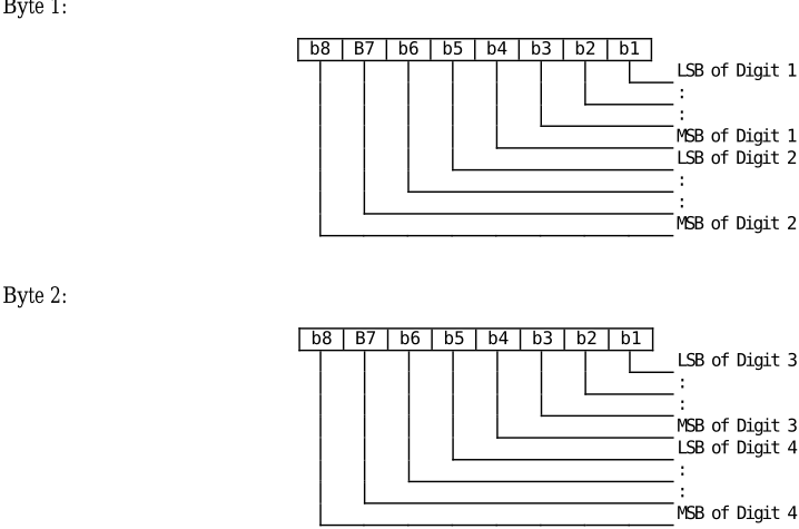
Etc.
13.3 EFPL (Preferred Languages)
This EF contains the codes for up to n languages. This information, determined by the user/operator, defines the preferred languages of the user, for the UICC, in order of priority.
| Identifier: '2F 05' | Structure: transparent | Mandatory | ||
|---|---|---|---|---|
| Mandatory | SFI: | |||
| File size: 2n bytes | Update activity: low | |||
| Access Conditions: | ||||
| READ | ALW | |||
| UPDATE | PIN | |||
| DEACTIVATE | ADM | |||
| ACTIVATE | ADM | |||
| Bytes | Description | M/O | Length | |
| 1 to 2 | 1 st language code (highest prior) | M | 2 bytes | |
| 3 to 4 | 2 nd language code | O | 2 bytes | |
| 2n-1 to 2n | nth language code (lowest prior) | O | 2 bytes | |
Coding: Each language code is a pair of alpha-numeric characters, defined in ISO 639 [6]. Each alpha-numeric character shall be coded on one byte using the SMS default 7-bit coded alphabet as defined in ETSI TS 123 038 [1] with bit 8 set to 0.
Unused language entries shall be set to 'FF FF'.
13.4 EFARR (Access Rule Reference)
This EF contains the access rules for files located under the MF in the UICC. If the security attribute tag '8B' is indicated in the FCP it contains a reference to a record in this file.
| Identifier: '2F06' | Structure: Linear fixed | Optional | ||
|---|---|---|---|---|
| SFI: Optional | ||||
| Record length: X bytes | Update activity: low | |||
| Access Conditions: | ||||
| READ | ALW | |||
| UPDATE | ADM | |||
| DEACTIVATE | ADM | |||
| ACTIVATE | ADM | |||
| Bytes | Description | M/O | Length | |
| 1 to X | Access Rule TLV data objects | M | X bytes | |
This EF contains one or more records containing access rule information according to the referenced format as defined in ISO/IEC 7816-4 [12]. Each record represents an access rule. Unused bytes in the record are set to 'FF'.
13.5 DFCD (Configuration Data)
13.5.0 Introduction
Clause 13.5 defines the files present in DF CD .
13.5.1 EFLAUNCH PAD
Support of this EF is mandatory for a UICC that supports the Smart Card Web Server [24].
This EF contains the data for one or more launch pads which can be integrated with the menu system (or other MMI facility) in order to give the user the opportunity to launch a browser session with the Smart Card Web Server. A terminal that supports the launch feature of the Smart Card Web Server shall read at least one of the launch pads stored in EF LAUNCH PAD and shall integrate them within the MMI in order to give the user the opportunity to launch a browser session with the Smart Card Web Server.
The launch pad comprises an alpha identifier, a browser identity, a URL and zero or more icon descriptors either for an icon stored in an EF or pointed to by a URI. The terminal shall present as many launch pads to the user as it is able, starting with the first one, according to the following rules:
- If no icon descriptor is provided, the terminal shall use a terminal specific default icon to present the launch pad to the user. The terminal may also display the alpha identifier together with the icon.
- If one or more icon descriptor(s) is/are provided, the terminal shall use the icon descriptors and if required the icon data retrieved from the referenced EF ICON to decide which of the icons is most appropriate for its menu system. If the terminal is able to use this data, if required so after appropriate resizing, it shall use the icon data to present the launch pad to the user. If indicated in the Icon qualifier the terminal may also display the alpha identifier together with the icon. If the icon data is not usable by the terminal, a default launch mechanism shall be used. The fact that the icon data from one of the referenced EF ICON was retrieved may be used by the UICC as an indication that the launch pad is presented to the user.
- As a minimum, terminals shall support the following icon format:
- PNG as specified in ISO/IEC 15948 [25];
- Icon size 32 x 32 pixel;
- indexed colour information with 8 bits per pixel.
When the UICC sends a REFRESH proactive command for this file, the procedure given above shall be followed.
| Identifier: '6F 01' | Structure: transparent | Optional | ||
|---|---|---|---|---|
| SFI: Optional | ||||
| File size: X bytes | Update activity: low | |||
| Access Conditions: | ||||
| READ | ALW | |||
| UPDATE | ADM | |||
| DEACTIVATE | ADM | |||
| ACTIVATE | ADM | |||
| Bytes | Description | M/O | Length | |
| 1 to N | 1 st launch pad | O | N bytes | |
| N+1 to N+M | 2 nd launch pad | O | M bytes | |
| … | … | |||
| X-K+1 to X | 'FF' padding | O | K bytes | |
Coding: Each launch pad is a constructed BER-TLV containing COMPREHENSION-TLVs as defined in ETSI TS 102 223 [4] and one additional TLV as defined below. It is coded as follows:
| Description | Clause in ETSI TS 102 223 [4] | M/O | Length |
|---|---|---|---|
| Launch pad tag 'A0' | - | M | 1 |
| Length (A+B+C+D+E1+E2+F1+F2+…) | - | M | 1 or 2 |
| Alpha identifier | 8.2 | M | A |
| Text Attribute | 8.72 | O | B |
| Browser Identity | 8.47 | O | C |
| URL (starting page) | 8.48 | M | D |
| First icon descriptor | see below | O | E1 |
| Second icon descriptor | see below | O | E2 |
| Third … | |||
| First icon descriptor URI | see below | O | F1 |
| Second icon descriptor URI | see below | O | F2 |
| Third … | |||
| … |
The Comprehension Required flag in the COMPREHENSION-TLVs shall be set to zero.
The alpha identifier contains the text to be displayed by the terminal together with a non-self-explanatory icon.
A text attribute contains formatting information intended to enhance the presentation of the alpha identifier.
The browser identity contains information about the type of browser to be used (e.g. HTML or WML browser).
The URL shall point to a page of the Smart Card Web Server [24].
The icon descriptor TLV contains information about the icon. Its tag value shall be '80'. Its value part shall be coded on 7 bytes as follows:
Byte 1: Icon qualifier:
- Contents:
- The icon qualifier indicates how the icon shall be used by the terminal.
- Coding:
- bit 1: 0 = icon is self-explanatory, i.e. if displayed, it replaces the alpha identifier; 1 = icon is not self-explanatory, i.e. if displayed, it shall be displayed together with the alpha identifier.
- bits 2 to 8 = 0 RFU.
Byte 2: Icon Coding Scheme:
- Contents:
- this byte identifies the image coding scheme that has been used in encoding the icon.
- Coding: Reference to a media type as defined in IETF RFC 2046 [26] and registered with IANA at http://www.iana.org/assignments/media-types/.
- '00' - other media type as defined in EF ICON ;
'01' - "image/png";
'02' - "image/jpeg";
'03' - "image/gif";
'04' - "image/tiff";
'05' - "image/vnd.microsoft.icon";
all other values - RFU.
Byte 3: Icon Width:
- Contents:
- this byte specifies the icon width, expressed in pixel.
- Coding:
- binary.
Byte 4: Icon Height:
- Contents:
- this byte specifies the icon height, expressed in pixel.
- Coding:
- binary.
Byte 5: Bits per pixel:
- Contents:
- this byte specifies the number of bits that are used to code each pixel.
- Coding:
- binary.
Bytes 6 and 7: File Identifier for icon EF:
- Contents:
- these bytes identify an EF which is the icon data file (see clause 13.5.2), holding the actual graphics data for this icon.
- Coding:
- Byte 6: high byte of Icon Data File Identifier; Byte 7: low byte of Icon Data File Identifier.
- NOTE: Care has to be taken that the information in the icon descriptor matches the data retrieved from the referenced EF ICON . Otherwise the terminal may revert to default behaviour.
The icon descriptor URI TLV contains information about the icon pointed to by a URI. Its tag value shall be '83'. Its value part shall be coded as follows:
Byte 1: Icon qualifier:
- Contents:
- The icon qualifier indicates how the icon shall be used by the terminal.
- Coding:
- Same as Icon qualifier for the case of pointer to the EF ICON file ID.
Byte 2 to end of the TLV: URI of the icon:
- Contents:
- URI with link to the icon.
- Coding:
- An octet string according to UTF-8 encoding rules (e.g. http://127.0.0.1:3516/files/smartcardicon.jpg). The URI shall point to a page of the Smart Card Web Server [24].
13.5.2 EFICON
This EF contains the data for one icon.
| Identifier: '6F XY' with XY = '40'..'7F' | Structure: transparent | Optional | |
|---|---|---|---|
| SFI: Optional | |||
| File size: X bytes | Update activity: low | ||
| Access Conditions: | |||
| READ | ALW ADM | ||
| UPDATE | |||
| DEACTIVATE | ADM | ||
| ACTIVATE | ADM | ||
| Description | M/O/C | ||
| Bytes | Length | ||
| 1 to M | Media type TLV (tag = | '80') | C M bytes |
| M+1 to M+N M+N+1 to X | Icon data TLV (tag 'FF' padding | = '81') | M N bytes O X-M-N bytes |
If no reference in EF LAUNCH PAD points to it, an icon file may contain arbitrary values.
Media type and icon data are coded as BER TLVs as defined in ETSI TS 101 220 [3]. The media type TLV shall be present if no media type is specified in the icon coding scheme of the entry in EF LAUNCH PAD that points to this file, else it is optional.
Media type value part:
- Contents:
- Text string specifying the icon encoding.
- Coding:
- As defined in IETF RFC 2046 [26] and registered with IANA at http://www.iana.org/assignments/mediatypes/media-types.xhtml e.g. "image/png".
Icon data value part:
- Contents:
- The graphical data of the icon.
- Coding:
- Binary data as defined for the respective media type.
13.6 EFUMPC (UICC Maximum Power Consumption)
This EF provides the value of the UICC maximum power consumption during the UICC session within the limits of clause 6.2.3 of the present document. In addition, this EF contains the value of the Operator defined time-out for the execution of any commands by the UICC if the terminal is not able to indicate it can supply the UICC maximum power consumption.
In case of a UICC supporting LSEs, the values of byte 1 and the value of bit 1 of byte 3 should be the same in all LSEs containing this EF.
| Identifier: '2F08' | Structure: transparent | Mandatory | ||
|---|---|---|---|---|
| SFI: Mandatory | ||||
| File size: 5 bytes | Update activity: low | |||
| Access Conditions: | ||||
| READ | ALW | |||
| UPDATE | ADM | |||
| DEACTIVATE | ADM | |||
| ACTIVATE | ADM | |||
| Bytes | Description | M/O | Length | |
| 1 | UICC maximum power consumption | M | 1 byte | |
| 2 | Operator defined time-out (T_OP) | M | 1 byte | |
| 3 | Additional information | M | 1 byte | |
| 4 to 5 | RFU | M | 2 bytes | |
- UICC maximum power consumption:
- Operator defined time out (T_OP):
Contents: Maximum power consumption of the UICC during the UICC session within the limits of clause 6.2.3 of the present document.
Coding: Coded in hexadecimal as below:
Bit 8: RFU, shall be set to '0'.
Bit 7-1:
'0A' to '3C'. Maximum power consumption of the UICC in mA.
Contents: Operator defined minimum time-out value the terminal shall set for the execution of any commands by the UICC if the terminal is not able to indicate it can supply the UICC maximum power consumption. The value is expressed in seconds.
Coding: Coded in hexadecimal between '01' and 'FF'.
- Additional information:
Contents: Indicates if the UICC requires an increased idle current during clock-stop-mode and if the UICC supports the UICC suspension procedure.
NOTE: In the scope of Release 12 drivers for increased idle current are e.g. high security capabilities together with extended features like additional crypto coprocessors, SWP interface and larger amount of volatile memory.
Coding:
- Bit 1: '0': UICC does not require increased idle current, '1': UICC requires increased idle current.
- Bit 2: '0': UICC does not support the UICC suspension procedure '1': UICC supports the UICC suspension procedure.
Bits 3-8: RFU, shall be set to '0'.
14 Application independent protocol
14.0 Introduction
The provisions of clause 14 apply to the logical UICC.
14.1 File related procedures
14.1.1 Reading an EF
Reading of an EF can be done in two different ways.
- If the short file identifiers are used the following procedure applies:
- If short file identifiers are used, Efs that support SFI within the Current Directory can be read without explicitly selecting the EF. The terminal selects the DF or ADF and sends a READ command. This contains the short file identifier of the EF to be read and the location of the data to be read. If the access condition for READ is fulfilled, the application sends the requested data contained in the EF to the terminal. If the access condition is not fulfilled, no data will be sent and an error code will be returned.
- If the short file identifiers are not used the following procedure applies:
- The terminal selects the EF and sends a READ command. This contains the location of the data to be read. If the access condition for READ is fulfilled, the application sends the requested data contained in the EF to the terminal. If the access condition is not fulfilled, no data will be sent and an error code will be returned.
14.1.2 Updating an EF
Updating of an EF can be done in two different ways:
- If the short file identifiers are used the following procedure applies:
- If short file identifiers are used, Efs that support SFI within the Current Directory can be updated without explicitly selecting the EF. The terminal selects the DF or ADF and sends an UPDATE command. This contains the short file identifier of the EF and the location of the data to be updated and the new data to be stored. If the access condition for UPDATE is fulfilled, the application updates the selected EF by replacing the existing data in the EF with that contained in the command. If the access condition is not fulfilled, the data existing in the EF will be unchanged, the new data will not be stored, and an error code will be returned.
- If the short file identifiers are not used the following procedure applies:
- The terminal selects the EF and sends an UPDATE command. This contains the location of the data to be updated and the new data to be stored. If the access condition for UPDATE is fulfilled, the application updates the selected EF by replacing the existing data in the EF with that contained in the command. If the access condition is not fulfilled, the data existing in the EF will be unchanged, the new data will not be stored, and an error code will be returned.
14.1.3 Increasing an EF
Increasing of an EF can be done in two different ways:
- If the short file identifiers are used the following procedure applies:
- If short file identifiers are used, Efs that support SFI within the Current Directory can be increased without explicitly selecting the EF. The terminal selects the DF or ADF and sends an INCREASE command. This contains the short file identifier of the EF and the value which has to be added to the contents of the last updated/increased record. If the access condition for INCREASE is fulfilled, the application increases the existing value of the EF by the data contained in the command, and stores the result. If the access condition is not fulfilled, the data existing in the EF will be unchanged and an error code will be returned.
- If the short file identifiers are not used the following procedure applies:
- The terminal selects the EF and sends an INCREASE command. This contains the value which has to be added to the contents of the last updated/increased record. If the access condition for INCREASE is fulfilled, the application increases the existing value of the EF by the data contained in the command, and stores the result. If the access condition is not fulfilled, the data existing in the EF will be unchanged and an error code will be returned.
- NOTE: The identification of the data within an EF to be acted upon by the above procedures is specified within the command. For the procedures in clauses 14.1.1 and 14.1.2 this data may have been previously identified using a SEARCH RECORD command, e.g. searching for an alphanumeric pattern.
14.2 PIN related procedures
14.2.0 Overview
NOTE: The present document specifies only the generic behaviour of a PIN. An application may create a set of PINs each with a specific behaviour.
A successful completion of one of the following procedures grants the access right of the corresponding PIN for an application session. This right is valid for all files within the application protected by this PIN.
After a third consecutive unsuccessful completion of one of the following procedures associated to the same PIN, not necessarily in the same application session, the PIN becomes "blocked" and if the PIN status is set "enabled", the access right previously granted by this PIN is lost immediately.
An access right is not granted if any of the following procedures are aborted.
14.2.1 PIN verification
The terminal checks the PIN and the following procedures apply:
- If the PIN status is set "enabled" and the PIN is "blocked", the procedure ends and is finished unsuccessfully.
- If the PIN status is set "disabled" and the PIN is "blocked", the procedure ends and is finished successfully. The terminal shall, however, accept applications which do not grant access rights when the PIN status is set "disabled" and the PIN is "blocked". In that case terminal shall consider those applications as "blocked".
- If the PIN status is set "disabled" and the PIN is not "blocked", the procedure is finished successfully.
- If the PIN status is set "enabled" and the PIN is not "blocked", the terminal uses the VERIFY PIN function. If the PIN presented by the terminal is equal to the corresponding PIN stored in the application, the procedure is finished successfully. If the PIN presented by the terminal is not equal to the PIN which protects the application, the procedure ends and is finished unsuccessfully.
14.2.2 PIN value substitution
The terminal checks the PIN and the following procedures apply:
- If the PIN status is set "disabled" or the PIN is "blocked", the procedure ends and is finished unsuccessfully.
- If the PIN status is set "enabled" and the PIN is not "blocked", the terminal uses the CHANGE PIN function. If the old PIN presented by the terminal is equal to the PIN which protects the application, the new PIN presented by the terminal is stored instead of the old one and the procedure is finished successfully.
- If the old PIN presented by the terminal and the PIN which protects the application are not identical, the procedure ends and is finished unsuccessfully.
14.2.3 PIN disabling
PIN enabling and disabling/disabling and replacement may be disallowed by an application. If it is allowed then the following procedures shall be followed:
- If either the PIN status is set "disabled" or the PIN is "blocked", the procedure ends and is finished unsuccessfully.
Disabling and replacement:
- If the application PIN is not "blocked" and both the application PIN and the alternative global key reference statuses are set to "enabled", the terminal uses the DISABLE PIN function. If the PIN presented by the terminal is equal to the PIN which protects the application, the status of the PIN is set "disabled" and the usage qualifier of the alternative global key reference is set to "use" ('08') and the procedure is finished successfully. If the PIN presented by the terminal is not equal to the PIN which protects the application, the procedure ends and is finished unsuccessfully.
Disabling, no replacement:
- If the PIN is not "blocked" and the PIN status is set "enabled", the terminal uses the DISABLE PIN function. If the PIN presented by the terminal is equal to the PIN which protects the application, the status of the PIN is set "disabled" and the procedure is finished successfully. If the PIN presented by the terminal is not equal to the PIN which protects the application, the procedure ends and is finished unsuccessfully.
14.2.4 PIN enabling
PIN enabling and disabling may be disallowed by an application. If it is allowed then the following procedures shall be followed:
- If either the PIN status is set "enabled" or the PIN is "blocked", the procedure ends and is finished unsuccessfully.
- If the PIN status is set "disabled" and the PIN is not "blocked", the terminal uses the ENABLE PIN function. If the PIN presented by the terminal is equal to the PIN which is assigned to the application, the status of the PIN is set "enabled" and the procedure is finished successfully. If the PIN presented by the terminal is not equal to the PIN which protects the application, the procedure ends and is finished unsuccessfully.
14.2.5 PIN unblocking
The execution of the PIN unblocking procedure is independent of whether or not the PIN is "blocked".
The terminal checks if the UNBLOCK PIN is "blocked". If the UNBLOCK PIN is "blocked", the procedure ends and is finished unsuccessfully.
If the UNBLOCK PIN is not "blocked", the terminal uses the UNBLOCK PIN function. If the UNBLOCK PIN presented by the terminal is equal to the corresponding UNBLOCK PIN of the application, the relevant PIN becomes "unblocked" and the procedure is finished successfully. If the UNBLOCK PIN presented by the terminal is not equal to the corresponding UNBLOCK PIN of the application, the procedure ends and is finished unsuccessfully.
14.3 Application selection procedures
14.3.1 Application selection by use of the EFDIR file
Application selection by use of the EF DIR file is the procedure where the terminal reads the content of the EF DIR file and presents the list of applications to the user whom can then make select one or more applications to activate.
The terminal performs the read procedure with EF DIR and presents the applications that it supports to the user who may make a selection. If only one supported application is found this may be implicitly selected.
14.3.2 Direct application selection
An application may be selected, without reading the content of the EF DIR file, by performing the SELECT procedure with the AID of the application to be selected.
14.3.3 Direct application selection with partial AID
See clause 8.5.1.2.
14.4 General application related procedures
14.4.1 Application session activation
The terminal performs the SELECT function with the AID of the selected application as a parameter.
If the SELECT function ends successfully the selected application's initialization procedure is executed. If the initialization procedure ends successfully the UICC enters the operation state. If the initialization procedure does not end successfully, the UICC remains in the application management state and sends an indication to the user that it was not possible to activate the selected application.
14.4.2 UICC application interrogation
The list of applications residing in the UICC can be read at any time when the UICC is not inactive.
Request: The terminal performs the read procedure with EF DIR .
14.4.3 UICC application session termination
An application session can be terminated at any time when the UICC is not inactive.
14.5 Miscellaneous procedures
14.5.1 UICC activation
After activation of the UICC the terminal requests the Preferred Language (EF PL ). The terminal shall execute the power negotiation procedure. If the terminal supports CAT, it shall perform the CAT initialization procedure. The terminal then performs an application selection procedure according to clause 14.3.
14.5.2 UICC presence detection
If an application present on the UICC has the requirement to ensure that the UICC has not been removed during a card session the following procedure applies. The terminal sends, at frequent intervals, a STATUS command on the UICC-terminal interface. The STATUS command shall be issued within a period of inactivity on the UICC-terminal interface. The period of inactivity and the conditions under which the presence detection takes place is specified by the applications active during the card session. Inactivity in this case is defined as starting at the end of the last communication or the last issued STATUS command. If no response data is received to this STATUS command the terminal shall take the appropriate actions after the work waiting time (T = 0) or block waiting time (T = 1) has expired as specified by the applications active. If the DF indicated in an error free response to a STATUS command is not the same as that which was indicated in the previous response, or accessed by the previous command, then the terminal shall take appropriate actions as specified by the applications active during the card session. This procedure shall be used in addition to a mechanical or other device used to detect the removal of a UICC.
In case of a UICC supporting LSEs, this procedure shall be performed for each LSE that requires presence detection.
14.5.3 UICC preferred language request
Request:
Update:
The terminal performs the read procedure with EF PL .
The terminal performs the update procedure with EF PL .
14.5.4 UICC logical channels
A UICC may offer the possibility to run several selectable applications in parallel. This is done with the logical channel mechanism. Only one selectable application can run at a given time in a given logical channel.
14.5.5 Power negotiation
The terminal shall attempt to select and read the UICC Maximum Power Consumption file (EF UMPC ).
If the file is present, the UICC is aware of the maximum power consumption values for Release 12 and higher. Else it is only aware of the values for pre-Release 12.
If the UICC supports the TERMINAL CAPABILITY command (which is mandatory for Release 12 and higher), the terminal shall send a TERMINAL CAPABILITY command indicating the maximum available power supply of the terminal within the range that the UICC is aware of.
14.5.6 UICC suspension
UICC suspension can be used by the terminal to suspend the UICC when access is not required for long periods of time, in order to reduce the overall power consumption. When the UICC is suspended, the terminal deactivates the contacts of the UICC, following the sequence specified in clause 4.5.2.
The procedure can be used only when it is indicated as supported by the UICC in the UICC Maximum Power Consumption file (EF UMPC ).
The terminal shall maintain the logical status as before the suspension and it shall resume the UICC for any event for which it had previously registered: this includes events registered with SET UP EVENT LIST or TIMER MANAGEMENT proactive command, as specified in ETSI TS 102 223 [4].
When the terminal needs to resume the UICC, it first performs the initial communication establishment procedures, as described in clause 6. The terminal can optionally check if the content of the EF ICCID matches the value used before the UICC was suspended. The terminal sends the SUSPEND UICC command with P1 = '01' and the Resume token received when the UICC was suspended earlier. The resume operation does not have impact on the parameters negotiated as part of the initial communication establishment procedures.
14.6 CAT related procedures
14.6.0 Scope of CAT related procedures
The higher level procedures, and contents and coding of the commands, are given in ETSI TS 102 223 [4]. Procedures relating to the transmission of commands and responses across the terminal-UICC interface are given in this clause. A UICC or terminal supporting CAT shall conform to the requirements given in this clause.
14.6.1 CAT Initialization procedure
A terminal supporting CAT shall send the TERMINAL PROFILE C-APDU. A UICC supporting CAT shall return the response status words (SW1 SW2) '90 00' or '91 XX'. If any other value is returned, the terminal shall assume that CAT is not supported. In case of proactive command pending, the terminal shall then start the proactive polling procedure with the default value.
14.6.2 Proactive polling
During idle mode the terminal shall send STATUS commands to the UICC at intervals no longer than the interval negotiated with the UICC (see ETSI TS 102 223 [4]). During a call the UICC presence detection applies. The default value for the proactive polling is the same as for the presence detection procedure.
In case of a UICC supporting LSEs, the terminal shall perform the proactive polling on every LSI where CAT was successfully initialized with the interval negotiated on each specific LSI.
14.6.3 Support of commands
A terminal supporting CAT shall support the commands TERMINAL PROFILE, ENVELOPE, FETCH and TERMINAL RESPONSE.
14.6.4 Support of response codes
A terminal supporting CAT shall support the response status words (SW1 SW2) '91 XX' and '93 00'. These responses shall never be used if the terminal does not support CAT.
14.6.5 Independence of applications and CAT tasks
Application and CAT operation shall be logically independent, both in the UICC and in the terminal. Specifically, this means:
- The currently selected EF and current record pointer in any active application shall remain unchanged, if still valid, as seen by the terminal, irrespective of any CAT activity.
- Between successive CAT related command-response pairs, other application (e.g. USIM) and UICC related command-response pairs can occur. The CAT task status shall remain unchanged by these command-response pairs.
14.6.6 Use of BUSY status response
If for any reason the CAT task of the UICC cannot process an ENVELOPE command issued by the terminal at present (e.g. other CAT processes are already running), the UICC can respond with a status response of '93 00'. The terminal may re-issue the command at a later stage.
The BUSY status response has no impact on e.g. USIM operation.
14.6.7 Additional processing time
The transport protocol provides a mechanism for the UICC to obtain additional processing time (i.e. NULL procedure byte for T = 0 and Work Waiting time extension (WTX) for T = 1) before supplying the response part of a command-response pair, during which time the terminal is unable to send further commands to the UICC.
If a CAT activity in the UICC runs for too long, this may prevent the terminal from sending e.g. USIM commands which are time-critical, e.g. INTERNAL AUTHENTICATE. A MORE TIME command is defined in ETSI TS 102 223 [4], which ensures that the USAT task in the UICC gets additional processing time, while at the same time freeing the UICC/terminal interface. The MORE TIME command should be used in preference to the transport protocol specific mechanisms for obtaining additional processing time.
15 Support of APDU-based UICC applications over USB
NOTE: Support for LSIs on USB is FFS.
If a card session is established over the Smart Card functional interface specified in ETSI TS 102 600 [18], the following provisions apply.
Clauses 6.3, 7.4, 8, 9, 10, 11, 13 and 14 of the present document apply. Clause 6.8 also applies, with the exception of the physical interface error detection and character repetition procedure. All application level requirements for APDU-based UICC applications (e.g. Telecom applications) and features (e.g. CAT) apply.
The request for additional processing time of clause 14.6.7 of the present document shall be performed by a USB command as described in ETSI TS 102 600 [18].
A reset is issued preferably by a logical reset command at the level of the Smart Card functional interface, as described in ETSI TS 102 600 [18], or by an electrical reset of the IC USB interface. In either case, the effect is logically equivalent to the effect of a reset according to clause 6.5.
Annex A (normative):
UCS2 coding of Alpha fields for files residing on the UICC
If 16 bit UCS2 characters as defined in ISO/IEC 10646 [17] are used in an alpha field, the coding can take one of three forms. If the terminal supports UCS2 coding of alpha fields in the UICC, the terminal shall support all three coding schemes for character sets containing 128 characters or less; for character sets containing more than 128 characters, the terminal shall at least support the first coding scheme. If the alpha field record contains GSM default alphabet characters only, then none of these schemes shall be used in that record. Within a record, only one coding scheme, either the GSM default alphabet (see ETSI TS 123 038 [1]), or one of the three described below, shall be used.
- If the first byte in the alpha string is '80', then the remaining bytes are 16 bit UCS2 characters, with the More Significant Byte (MSB) of the UCS2 character coded in the lower numbered byte of the alpha field, and the Less Significant Byte (LSB) of the UCS2 character is coded in the higher numbered alpha field byte, i.e. Byte 2 of the alpha field contains the More Significant Byte (MSB) of the first UCS2 character, and Byte 3 of the alpha field contains the Less Significant Byte (LSB) of the first UCS2 character (as shown below). Unused bytes shall be set to 'FF', and if the alpha field is an even number of bytes in length, then the last (unusable) byte shall be set to 'FF'.
EXAMPLE 1:
| Byte 1 | Byte 2 | Byte 3 | Byte 4 | Byte 5 | Byte 6 | Byte 7 | Byte 8 | Byte 9 |
| '80' | Ch1 MSB | Ch1 LSB | Ch2 MSB | Ch2 LSB | Ch3 MSB | Ch3 LSB | 'FF' | 'FF' |
- If the first byte of the alpha string is set to '81', then the second byte contains a value indicating the number of characters in the string, and the third byte contains an 8 bit number which defines bits 15 to 8 of a 16 bit base pointer, where bit 16 is set to zero, and bits 7 to 1 are also set to zero. These sixteen bits constitute a base pointer to a "half-page" in the UCS2 code space, to be used with some or all of the remaining bytes in the string. The fourth and subsequent bytes in the string contain codings as follows; if bit 8 of the byte is set to zero, the remaining 7 bits of the byte contain a GSM Default Alphabet character, whereas if bit 8 of the byte is set to one, then the remaining seven bits are an offset value added to the 16 bit base pointer defined earlier, and the resultant 16 bit value is a UCS2 code point, and completely defines a UCS2 character.
EXAMPLE 2:
| Byte 1 | Byte 2 | Byte 3 | Byte 4 | Byte 5 | Byte 6 | Byte 7 | Byte 8 | Byte 9 |
| '81' | '05' | '13' | '53' | '95' | 'A6' | 'XX' | 'FF' | 'FF' |
In the above example:
- Byte 2 indicates that there are 5 characters in the string.
- Byte 3 indicates bits 15 to 8 of the base pointer, and indicates a bit pattern of 0hhh hhhh h000 0000 as the 16 bit base pointer number. Bengali characters for example start at code position 0980 (0000 1001 1000 0000), which is indicated by the coding '13' in Byte 3 (shown by the bold digits).
- Byte 4 indicates GSM Default Alphabet character '53', i.e. 'S'.
- Byte 5 indicates a UCS2 character offset to the base pointer of '15', expressed in binary as follows 001 0101, which, when added to the base pointer value results in a sixteen bit value of 0000 1001 1001 0101, i.e. '0995', which is the Bengali letter KA.
- Byte 8 contains the value 'FF', but as the string length is 5, this is a valid character in the string, where the bit pattern 111 1111 is added to the base pointer, yielding a sixteen bit value of 0000 1001 1111 1111 for the UCS2 character (i.e. '09FF').
- If the first byte of the alpha string is set to '82', then the second byte contains a value indicating the number of characters in the string, and the third and fourth bytes contain a 16 bit number which defines the complete 16 bit base pointer to a "half-page" in the UCS2 code space, for use with some or all of the remaining bytes in the string. The fifth and subsequent bytes in the string contain codings as follows; if bit 8 of the byte is set to zero, the remaining 7 bits of the byte contain a GSM Default Alphabet character, whereas if bit 8 of the byte is set to one, the remaining seven bits are an offset value added to the base pointer defined in bytes three and four, and the resultant 16 bit value is a UCS2 code point, and defines a UCS2 character.
EXAMPLE 3:
| Byte 1 | Byte 2 | Byte 3 | Byte 4 | Byte 5 | Byte 6 | Byte 7 | Byte 8 | Byte 9 |
| '82' | '05' | '05' | '30' | '2D' | '82' | 'D3' | '2D' | '31' |
In the above example:
- Byte 2 indicates that there are 5 characters in the string.
- Bytes 3 and 4 contain a sixteen bit base pointer number of '0530', pointing to the first character of the Armenian character set.
- Byte 5 contains a GSM Default Alphabet character of '2D', which is a dash "-".
- Byte 6 contains a value '82', which indicates it is an offset of '02' added to the base pointer, resulting in a UCS2 character code of '0532', which represents Armenian character Capital Ben.
- Byte 7 contains a value 'D3', an offset of '53', which when added to the base pointer results in a UCS2 code point of '0583', representing Armenian Character small Piwr.
Annex B (informative): Main states of a UICC
A UICC complying with the present document has the following states of operation:
- "Inactive" - In this state the UICC is powered off.
- "Application management" - In this state it is possible to start/end one or more application-session(s) as well as retrieve the list of applications in the UICC. This state can be entered at any time when the UICC is not in the inactive state and left when the PIN access condition for all the selected applications has been verified.
- "Operation" - This state is entered after the application session activation procedure for at least one application has ended successfully.
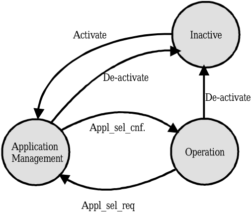
Annex C (informative):
APDU protocol transmission examples
C.1 Exchanges Using T = 0
C.1.0 Overview
The following examples illustrate exchanges of data and procedure bytes between the terminal and the UICC when standard logical channels are used (see clause 10.1.1).
Note the following:
- The use of procedure bytes '60' and is not illustrated. INS
- [Data(X)] means X bytes of data.
- Case 2 and 4 commands may have Le = '00' requesting the return of all data from the UICC up to the maximum available.
The examples in clauses C.1.1 to C.1.4 illustrate typical exchanges using case 1 to 4 commands. The examples in the clauses C.1.5 and C.1.6 illustrate the more extensive use of procedure bytes '61 XX' when used with cases 2 and 4 commands. The example in clause C.1.7 illustrates a warning condition with a case 4 command.
C.1.1 Case 1 command
A C-APDU of {CLA INS P1 P2} is passed from the terminal to the UICC (note that P3 of the C-TPDU is set to '00').

An R-APDU of {90 00} is returned from the UICC to the terminal.
C.1.2 Case 2 command
In this first example, a C-APDU of {CLA INS P1 P2 Le = 00} is passed from the terminal to the UICC with Luicc < 256 bytes.

An R-APDU of {[Data(Luicc)] 90 00} is returned from the UICC to the terminal.
In this second example, a C-APDU of {CLA INS P1 P2 Le = 00} is passed from the terminal to the UICC with Luicc = 256 bytes.

An R-APDU of {[Data(Luicc)] 90 00} is returned from the UICC to the terminal.
C.1.3 Case 3 command
A C-APDU of {CLA INS P1 P2 Lc [Data(Lc)]} is passed from the terminal to the UICC.

An R-APDU of {90 00} is returned from the UICC to the terminal.
C.1.4 Case 4 command
A C-APDU of {CLA INS P1 P2 Lc [Data (Lc)] Le = 00} is passed from the terminal to the UICC.
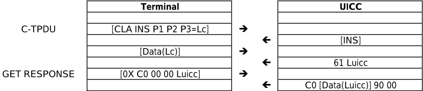
An R-APDU of {[Data(Luicc)] 90 00} is returned from the UICC to the terminal.
The GET RESPONSE command is sent on the same logical channel as the C-TPDU.
C.1.5 Case 2 commands Using the '61' and '6C' procedure bytes
A C-APDU of {CLA INS P1 P2 Le = 00} is passed from the terminal to the UICC with Luicc < 256 bytes.
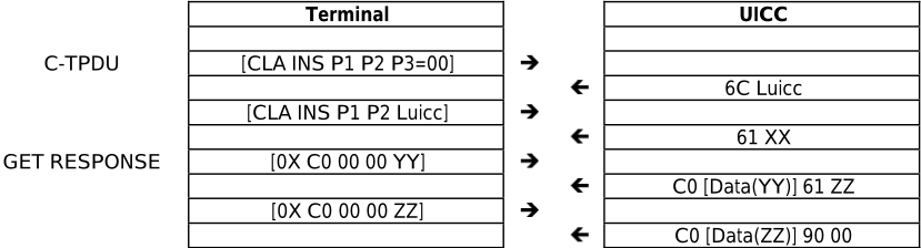
Where YY ≤ XX,
An R-APDU of {[Data(YY + ZZ)] 90 00} is returned from the UICC to the terminal.
The GET RESPONSE command is sent on the same logical channel as the C-TPDU.
C.1.6 Case 4 command Using the '61' procedure byte
A C-APDU of {CLA INS P1 P2 Lc [Data Lc] Le = 00} is passed from the terminal to the UICC.
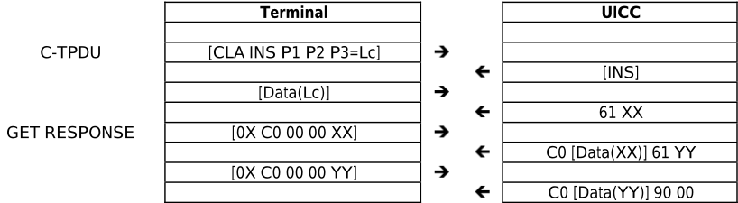
An R-APDU of {[Data(XX + YY)] 90 00} is returned from the UICC to the terminal.
The GET RESPONSE command is sent on the same logical channel as the C-TPDU.
C.1.7 Case 4 command with warning condition
A C-APDU of {CLA INS P1 P2 Lc [Data Lc] Le = 00} is passed from the terminal to the UICC.
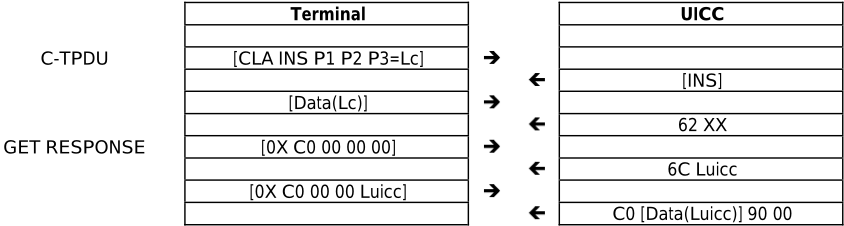
| Terminal | UICC | ||
|---|---|---|---|
| C-TPDU | [CLA INS P1 P2 P3=Lc] | | |
| | [INS] | ||
| [Data(Lc)] | | ||
| | 62 XX | ||
| GET RESPONSE | [0X C0 00 00 00] | | |
| | 6C Luicc | ||
| [0X C0 00 00 Luicc] | | ||
| | C0 [Data(Luicc)] 90 00 |
An R-APDU of {[Data(Luicc)] 62 XX} is returned from the UICC to the terminal containing the data returned together with the warning status bytes.
The GET RESPONSE command is sent on the same logical channel as the C-TPDU.
Annex D (informative): ATR examples
This annex gives examples of ATRs that can be returned by a UICC after a reset.
| Character | Value | Description |
|---|---|---|
| TS | '3B' or '3F' | Indicates direct or inverse convention |
| T0 | '97' | TA1 and TD1 are present 7 bytes of historical bytes |
| TA1 | '95' | Clock rate conversion factor FI=9 (F=512) Baud rate adjustment factor DI=5 (D=16) |
| TD1 | '80' | TD2 only is present |
| TD2 | '1F' | TA3 only is present Global interface bytes following |
| TA3 | '42' | Clock stop supported (low electrical state) 3V UICC |
| T1 | '80' | |
| T2 | '31' | Card data services |
| T3 | 'A0' | SELECT by AID supported EFDIR present |
| T4 | '73' | Card capabilities |
| T5 | 'BE' | SFI supported |
| T6 | '21' | Data Coding Byte |
| T7 | '15' | No extended Lc and Le 6 logical channels supported |
| TCK | 'XX' | Check byte |
| Character | Value | Description |
|---|---|---|
| TS | '3B' or '3F' | Indicates direct or inverse convention |
| T0 | '97' | TA1, and TD1 are present 7 bytes of historical bytes |
| TA1 | '95' | Clock rate conversion factor FI=9 (F=512) Baud rate adjustment factor DI=5 (D=16) |
| TD1 | '80' | Only TD2 is present Protocol T = 0 supported by UICC |
| TD2 | 'B1' | TA3, TB3 and TD3 are present Protocol T = 1 supported by UICC |
| TA3 | 'FE' | IFSC is 254 bytes long |
| TB3 | '00' | Block Waiting Integer=0 Character Waiting Integer=0 |
| TD3 | '1F' | Only TA4 is present Global interface bytes following |
| TA4 | '42' | Clock stop supported (low electrical state) 3V UICC |
| T1 | '80' | |
| T2 | '31' | Card data services |
| T3 | 'A0' | SELECT by AID supported EFDIR present |
| T4 | '73' | Card capabilities |
| T5 | 'BE' | SFI supported |
| T6 | '21' | Data Coding Byte |
| T7 | '17' | No extended Lc and Le More than 8 logical channels supported |
| TCK | 'XX' | Check byte |
| Character | Value | Description |
|---|---|---|
| TS | '3B' or '3F' | Indicates direct or inverse convention |
| T0 | '97' | TA1, and TD1 are present 7 bytes of historical bytes |
| TA1 | '95' | Clock rate conversion factor FI=9 (F=512) Baud rate adjustment factor DI=5 (D=16) |
| TD1 | '91' | TA2 and TD2 are present Protocol T = 1 supported by UICC |
| TA2 | '81' | Protocol T = 1 used in specific mode Parameters indicated by the interface bytes, and card is not able to change mode |
| TD2 | 'B1' | TA3, TB3 and TD3 are present Protocol T = 1 supported by UICC |
| TA3 | 'FE' | IFSC is 254 bytes long |
| TB3 | '00' | Block Waiting Integer=0 Character Waiting Integer=0 |
| TD3 | '1F' | Only TA4 is present Global interface bytes following |
| TA4 | '42' | Clock stop supported (low electrical state) |
| T1 | '80' | |
| T2 | '31' | Card data services |
| T3 | 'A0' | SELECT by AID supported EF DIR present |
| T4 | '73' | Card capabilities |
| T5 | 'BE' | SFI supported |
| T6 | '21' | Data Coding Byte |
| T7 | '00' | No extended Lc and Le No Logical channels supported |
| TCK | 'XX' | Check byte |
Annex E (informative):
Security attributes mechanisms and examples
E.1 Coding
Two codings are defined:
- a compact coding based on bitmaps;
- an expanded coding which is an extension of the compact coding with intermediate scope containing bitmap and TLV list management.
The security conditions for bits not set to '1' in the AM byte are set to NEVer by default.
E.2 Compact format
E.2.0 Coding
The compact format access rule is indicated by tag '8C' in the FCP. An access rule in this format is encoded with:
- an AM byte as defined in ISO/IEC 7816-4 [12];
- one or more SC bytes as defined in ISO/IEC 7816-4 [12].
E.2.1 AM byte
The AM byte conveys two types of information:
- interpretation of the AM byte itself;
- number of SC bytes in the access rule.
If b8 in the AM byte is set to '0' the AM byte is followed by a number of SC bytes equal to the number of bits set to '1' in the AM byte (excluding b8). Each SC bytes codes the conditions relevant to a set of commands, in the same order (b7 to b1) as in the AM byte. When b8 is set to '1' the usage of b7 to b4 is proprietary.
When multiple sets of an AM byte and one or more corresponding SC bytes are present in the value field of the DO, tag '8C', they represent an OR condition.
E.2.2 SC byte
The SC byte specifies which security mechanisms are necessary to conform to the access rules, see ISO/IEC 7816-4 [12]. The 4 most significant bits (b8 to b5) indicate the required security condition. An SE may be specified in bits b4 to b1. If an SE is specified, the mechanisms that may be defined in it for external authentication, user authentication and command protection are used, if indicated by bits b4 to b1.
If bit b8 is set to '1' all conditions in bits b7 to b5 need to be satisfied. If bit b8 is set to '0' at least one of the conditions set in bits b7 to b5 need to be satisfied. If b7 is set to '1', the CRT of the SE indicated in bits b4 to b1 describes whether secure messaging applies to the command APDU, the response APDU or both.
E.2.3 Examples
For Efs with the access condition ALW for READ and UPDATE the security attribute would look as follows:
| Tag | L | AM | SC | SC |
| '8C' | '03' | '03' | '00' | '00' |
For Efs with the access condition ALW for READ and NEV for all other access conditions the security attribute would look as follows:
| Tag | L | AM | SC |
| '8C' | '02' | '01' | '00' |
For EF DIR and EF ICC the access rule would be as follows. READ is set to ALW and UPDATE, DEACTIVATE and ACTIVATE is set to ADM. The ADM condition is indicated as a user authentication. The key reference is implicitly known.
| Tag | L | AM | SC | SC | SC | SC |
| '8C' | '05' | '1B' | '90' | '90 | '90' | '00' |
E.3 Expanded format
E.3.0 Coding
In the expanded format AM_DOs and SC_DOs are used to create the access rules. The expanded format access rule is indicated by tag 'AB' in the FCP. An access rule in this format is encoded with an AM_DO followed by a sequence of SC_DOs.
E.3.1 AM_DO
The AM_DO is defined in ISO/IEC 7816-4 [12]. The content of the AM_DO is defined by the tag value. Tag '80' indicates that the AM_DO contains an AM byte. Tags '81' to '8F' indicates that the AM_DO contains a command description. The content of the command description is dependent upon the tag value as defined in ISO/IEC 7816-4 [12]. Tag '9C' indicates that the AM_DO contains a proprietary state machine description.
When multiple sets of an AM_DO and one or more corresponding SC_DOs are present in the value field of the DO, tag 'AB', they represent an OR condition.
E.3.2 SC_DO
The SC_DO is defined in ISO/IEC 7816-4 [12]. The SC_DO definition contains an OR and an AND template. Several SC_DOs may be attached to a particular operation:
- If the SC_DOs are encapsulated in an OR template, then only one of the security conditions has to be fulfilled for the operation to be allowed.
- If the SC_DOs are not to be encapsulated in an OR template or if the SC_DOs are encapsulated in an AND template, then all security conditions have to be fulfilled before the operation is allowed.
E.3.3 Access rule referencing
Access rules in expanded format (AM_DOs and SC_DOs) may be stored in a linear fixed EF, each record contain one or more rules, as defined in ISO/IEC 7816-4 [12]. The access rule file may be an internal file, referenced implicitly, or may be referenced explicitly, e.g. by a file ID. The access rule stored in a file is indicated by tag '8B' in the FCP. The value of this DO contains at least one record number, called ARR. The DO can contain:
- A single byte containing the record number of the rule, valid if the access rule file is (implicitly) known.
- Three bytes containing two bytes with the File ID of the access rule file followed by one byte with the record number for the access rule.
- If the value filed is coded with a length of 2 + n x 2, for n > 1, it contains one or more SEID/ARR pairs, where the SEID codes the SE number on one byte. For each SE number, the access rules indicated in the ARR following its SE number are valid.
E.3.4 Examples
The access rule for EF PL would look as follows. The READ and SEARCH access condition is ALWays. The UPDATE access condition is application1 PIN or application2 PIN.
| Tag | L | AM_DO Tag | L | V | OR Tag | L | SC_DO Tag | L | Key Ref Tag | L | V | Qualifier Tag L | V | SC_DO Tag | L | Ref Tag | L | V | Usage Qualifier Tag | L | V | AM_DO Tag | L | SC_DO Tag | V L | ||||||
|---|---|---|---|---|---|---|---|---|---|---|---|---|---|---|---|---|---|---|---|---|---|---|---|---|---|---|---|---|---|---|---|
| Key | |||||||||||||||||||||||||||||||
| Usage | |||||||||||||||||||||||||||||||
| '1A' | '80' | '02' | '01 | '95' | 'A4' | '06' | '83' | '01' | '95' | '01' | '02' | '01' | '90' | ||||||||||||||||||
| 'AB' | '01' | 'A0' | '10' | 'A4' | '06' | '83' | '01' | '01' | '08' | '80' | '01' | '08' | '00' |
Annex F (informative):
Example of contents of EFARR '2F06'
F.1 Sample content of the EFARR
This clause contains an example of the contents of EF ARR '2F06'.
| ARR Record | Appli cable | Access | AM_ | Value | SC_DO CRT Tag | Security Condition | Len | Value | ||||||
|---|---|---|---|---|---|---|---|---|---|---|---|---|---|---|
| Condition | DO | LEN | Key Ref Tag | Len | Value | Usage Qualifier Tag | Len | Value | ||||||
| 01 | EF | READ UPDATE/ DE-ACTIVATE/ ACTIVATE | '80' '80' | '01' '01' | '01' '1A' | '90' 'A4' | ALW Level 5 | '00' '06' | '83' | '01' | '0X' | '95' | '01' | 'YY' |
| 02 | EF | READ DEACTIVATE/ ACTIVATE | '80' '80' | '01' '01' | '01' '18' | '90' 'A4' | ALW Level 5 | '00' '06' | '83' | '01' | '0X' | '95' | '01' | 'YY' |
| 03 | EF | READ UPDATE DEACTIVATE/ ACTIVATE | '80' '80' '80' | '01' '01' '01' | '01' '02' '18' | '90' 'A4' 'A4' | ALW PIN Level 5 | '00' '06' '06' | '83' '83' | '01' '01' | '01' '0X' | '95' '95' | '01' '01' | '01' 'YY' |
The value X in table F.1 is according to level 5 in table 9.3. The value 'YY' in table F.1 is in accordance with ISO/IEC 7816-4 [12].
As an example, those records could be used as follows: the first record of EF ARR can be the access rule of EF DIR , the second record of EF ARR can be the access rule of EF ICCID , the third record of EF ARR can be the access rule of EF PL .
Annex G (informative):
Access Rules Referencing (ARR)
G.1 Sample content of EFARR
This clause contains a set of access rule examples that are stored in EF ARR . The access rules are referenced using tag '8B' in the FCP.
The following definitions apply:
- the application PIN is referred to as PIN Appl. 1 global (key reference '01');
- the UICC supports the usage of a universal PIN, see clause 9.4.1, that is referred to as UNIVERSAL PIN (key reference '11');
- the application PIN2 is referred to as Second PIN Appl.1 local (key reference '81');
- access condition ADM is referenced as Level 5/Level 6 (key reference 'YZ') where:
- 'Y' = '0' for Level 5 and 'Y' = '8' for Level 6;
- 'Z' = 'A' to 'E' for Level5 and Level 6;
- the value 'XX' for the usage qualifier for key reference value 'YZ' is according to ISO/IEC 7816-4 [12].
| ARR | Appli- | Access | Value | SC_DO CRT | Security Condition | |||||||||
|---|---|---|---|---|---|---|---|---|---|---|---|---|---|---|
| Record | cable | Condition | AM_DO | Len | Tag | Len | Key Ref Tag | Len | Value | Value Usage Qualifier Tag | Len | Value | ||
| 01 | EF | READ | '80' | '01' | '01' | '90' | ALW | '00' | - | - | - | - | - | - |
| 02 | EF | READ UPDATE DEACTIVATE / ACTIVATE | '80' '80' '80' | '01' '01' '01' | '01' '02' '18' | '90' 'A4' 'A4' | ALW PIN Appl 1 global Level 5/Level 6 | '00' '06' '06' | '83' '83' | '01' '01' | '01' 'YZ' | '95' '95' | '01' '01' | '08' 'XX' |
| 03 | EF | READ UPDATE/ DEACTIVATE / ACTIVATE | '80' '80' | '01' '01' | '01' '1A'' | 'A4' 'A4' | PIN Appl 1 global Level 5/Level 6 | '06' '06' | '83' '83' | '01' '01' | '01' 'YZ' | '95' '95' | '01' '01' | '08' 'XX' |
| 04 | EF | READ/UPDA TE DEACTIVATE / ACTIVATE | '80' '80' | '01' '01' | '03' '18' | 'A4' 'A4' | PIN Appl 1 global Level 5/Level 6 | '06' '06' | '83' '83' | '01' '01' | '01' 'YZ' | '95' '95' | '01' '01' | '08' 'XX' |
| 05 | EF | READ UPDATE DEACTIVATE / ACTIVATE | '80' '80' '80' | '01' '01' '01' | '01' '02' '18' | 'A4' 'A4' 'A4' | PIN Appl 1 global PIN2 Appl 1 local Level 5/Level 6 | '00' '06' '06' | '83' '83' '83' | '01' '01' '01' | '01' '81' 'YZ' | '95' '95' '95' | '01' '01' '01' | '08' '08' 'XX' |
| 06 | EF | READ UPDATE/ DEACTIVATE / ACTIVATE | '80' '80' | '01' '01' | '01' '1A'' | '90' 'A4' | ALW Level 5/Level 6 | '00' '06' | '83' | '01' | 'YZ' | '95' | '01' | 'XX' |
| 07 | EF | READ/UPDA TE/ ACTIVATE DEACTIVATE | '80' '80' | '01' '01' | '13' '08' | 'A4' 'A4' | PIN Appl 1 global Level 5/Level 6 | '06' '06' | '83' '83' | '01' '01' | '01' 'YZ' | '95' '95' | '01' '01' | '08' 'XX' |
| 08 | EF | READ/UPDA TE/ ACTIVATE/ DEACTIVATE | '80' | '01' | '1B' | 'A4' | Level 5/Level 6 | '06' | '83' | '01' | 'YZ' | '95' | '01' | 'XX' |
| 09 | EF | READ/UPDA TE DEACTIVATE | '80' '80' | '01' '01' | '03' '18' | 'A4' 'A4' | PIN Appl 1 global Level 5/Level 6 | '06' '06' | '83' '83' | '01' '01' | '01' 'YZ' | '95' '95' | '01' '01' | '08' 'XX' |
| / ACTIVATE INCREASE | '84' | '01' | '32' | 'A4' | PIN Appl 1 global | '06' | '83' | '01' | '01' | '95' | '01' | '08' | ||
| ARR Record | Appli- | Access | AM_DO | Value | SC_DO CRT Tag | Security Condition | Value | |||||||
| cable | Condition | Len | Len | Key Ref Tag | Len | Value | Usage Qualifier Tag | Len | Value | |||||
| 10 | EF | READ/UPDA TE DEACTIVATE / ACTIVATE | '80' '80' '84' | '01' '01' '01' | '03' '18' '32' | 'A4' 'A4' 'A4' | PIN Appl 1 global Level 5/Level 6 PIN2 Appl 1 | '06' '06' '06' | '83' '83' '83' | '01' '01' '01' | '01' 'YZ' '81' | '95' '95' '95' | '01' '01' '01' | '08' 'XX' '08' |
| 11 | EF | INCREASE READ UPDATE DEACTIVATE / ACTIVATE | '80' '80' '80' | '01' '01' '01' | '01' '02' '18' | '90' 'A4' 'A4' | global ALW Universal PIN Level 5/ Level 6 | '00' '06' '06' | '83' '83' | '01' '01' | '11' 'YZ' | '95' '95' | '01' '01' | '08' 'XX' |
| 12 | EF | READ UPDATE/ DEACTIVATE / | '80' '80' | '01' '01' | '01' '1A'' | 'A4' 'A4' | Universal PIN Level 5/ Level 6 | '06' '06' | '83' '83' | '01' '01' | '11' 'YZ' | '95' '95' | '01' '01' | '08' 'XX' |
| 13 | EF | ACTIVATE READ/UPDA TE DEACTIVATE / ACTIVATE | '80' '80' | '01' '01' | '03' '18' | 'A4' 'A4' | Universal PIN Level 5/ Level 6 | '06' '06' | '83' '83' | '01' '01' | '11' 'YZ' | '95' '95' | '01' '01' | '08' 'XX' |
| 14 | EF | READ UPDATE DEACTIVATE / ACTIVATE | '80' '80' '80' | '01' '01' '01' | '01' '02' '18' | 'A4' 'A4' 'A4' | Universal PIN PIN2 Appl 1 local Level 5/Level 6 | '00' '06' '06' | '83' '83' '83' | '01' '01' '01' | '11' '81' 'YZ' | '95' '95' '95' | '01' '01' '01' | '08' '08' 'XX' |
| 15 | EF | READ UPDATE/ DEACTIVATE / ACTIVATE | '80' '80' | '01' '01' | '01' '1A'' | '90' 'A4' | ALW Level 5/Level 6 | '00' '06' | '83' | '01' | 'YZ' | '95' | '01' | 'XX' |
| 16 | EF | READ/UPDA TE/ ACTIVATE DEACTIVATE | '80' '80' | '01' '01' | '13' '08' | 'A4' 'A4' | Universal PIN Level 5/Level 6 | '06' '06' | '83' '83' | '01' '01' | '11' 'YZ' | '95' '95' | '01' '01' | '08' 'XX' |
| 17 | EF | READ/UPDA TE/ ACTIVATE/ DEACTIVATE | '80' | '01' | '1B' | 'A4' | Level 5/Level 6 | '06' | '83' | '01' | 'YZ' | '95' | '01' | 'XX' |
| 18 | EF | READ/UPDA TE DEACTIVATE / ACTIVATE | '80' '80' '84' | '01' '01' '01' | '03' '18' '32' | 'A4' 'A4' 'A4' | Universal PIN Level 5/Level 6 Universal PIN | '06' '06' '06' | '83' '83' '83' | '01' '01' '01' | '11' 'YZ' '11' | '95' '95' '95' | '01' '01' '01' | '08' 'XX' '08' |
| 19 | EF | INCREASE READ/UPDA TE DEACTIVATE / | '80' '80' | '01' '01' | '03' '18' | 'A4' 'A4' | Universal PIN Level 5/Level 6 | '06' '06' | '83' '83' | '01' '01' | '11' 'YZ' | '95' '95' | '01' '01' | '08' 'XX' |
| ACTIVATE INCREASE | '84' | '01' | '32' | 'A4' | PIN2 Appl 1 global | '06' | '83' | '01' | '81' | '95' | '01' | '08' | ||
| ARR Record | Appli- | Access | AM_ DO | L | V | SC_DOCRT Tag | Security Condition | L | SC_DOCRT Tag | L | SC_DOCRT Tag L | Value | Value | |||||||||
|---|---|---|---|---|---|---|---|---|---|---|---|---|---|---|---|---|---|---|---|---|---|---|
| cable | Condition | Key Ref Tag | L V | Usage Qualifier Tag | L V | Key Ref Tag | L | V Usage Qualifier Tag | L | V | ||||||||||||
| 01 | EF | READ | '80' | '01' | '01' | '90' | ALW | '00' | - | - - | - | - - | - | - | - - | - | - | |||||
| 02 | EF | READ UPDATE DEACTIVATE/ ACTIVATE | '80' '80' '80' | '01' '01' '01' | '01' '02' '18' | '90' 'A0' 'A4' | ALW PIN Appl 1 global OR PIN Appl 2 Level 5 | '00' '10' '06' | 'A4' | '06' '83' '83' | '01' '01' '01' '0Z' | '95' '95' | '01' '01' '08' 'XX' | 'A4' | '06' | '83' | '01' | '02' '95' | '01' | '08' | ||
| 03 | EF | READ UPDATE/ DEACTIVATE/ ACTIVATE | '80' '80' | '01' '01' | '01' '1A'' | 'A0' 'A4' | PIN Appl 1 global OR PIN Appl 2 Level 5 | '10' '06' | 'A4' | '83' '83' | '01' '01' '01' '0Z' | '95' '95' | '01' '01' '08' 'XX' | 'A4' | '06' | '83' | '01' | '02' | '95' | '01' | '08' | |
| 04 | EF | READ/UPDATE DEACTIVATE/ ACTIVATE | '80' '80' | '01' '01' | '03' '18' | 'A0' 'A4' | PIN Appl 1 global OR PIN Appl 2 Level 5 | '10' '06' | 'A4' | '83' '83' | '01' '01' '01' '0Z' | '95' '95' | '01' '01' '08' 'XX' | 'A4' | '06' '83' | '01' | '02' | '95' | '01' | '08' | ||
| 05 | EF | READ UPDATE/ DEACTIVATE/ ACTIVATE | '80' '80' | '01' '01' | '01' '1A'' | '90' 'A4' | ALW Level 5 | '00' '06' | '83' | '01' '0Z' | '95' | '01' 'XX' | ||||||||||
| 06 | EF | READ/ UPDATE/ ACTIVATE DEACTIVATE | '80' '80' | '01' '01' | '13' '08' | 'A0' 'A4' | PIN Appl 1 global OR PIN Appl 2 | '10' '06' | 'A4' | '83' '83' '01' '01' | '01' '0Z' | '95' '95' | '01' '01' '08' 'XX' | 'A4' | '06' | '83' | '01' | '02' | '95' | '01' | '08' | |
| 07 | EF | READ/UPDATE/ DEACTIVATE/ ACTIVATE | '80' | '01' | '1B' | 'A4' | Level 5 Level 5 | '06' | '83' '01' | '0Z' | '95' | '01' 'XX' | ||||||||||
G.2 Example of access rule referencing with SE ID
This clause describes an example of the usage of the access rule referencing method using SE ID. Table G.1 is considered to be the EF(ARR) file for this example.
Assume an application uses PIN Application 1 Global as its application PIN. In addition, this application allows the replacement of its application PIN by the Universal PIN. EF(example) is an elementary file part of this application and has the following access conditions:
- READ: Always.
- UPDATE: PIN application 1 Global.
- ACTIVATE/DEACTIVATE: level 5 or 6.
The security attributes returned after the selection of EF(example) then contains a reference to record 2 of table G.1 for SE 01 and a reference to record 11 of table G.1 for SE 00.
Annex H (normative):
List of SFI Values assigned in ETSI TS 102 221
H.1 List of SFI Values at the MF Level
| File Identifier | SFI | Description |
|---|---|---|
| '2FE2' | '02' | ICC Identification (EF ICCID ) |
| '2F05' | '05' | Preferred Languages (EF PL ) |
| '2F06' | '06' | Access Rules Reference (EF ARR ) |
| '2F07' | '07' | Environmental Classes (EF ENV-CLASSES) (specified in ETSI TS 102 671 [27]) |
| '2F08' | '08' | UICC Maximum Power Consumption (EF UMPC ) |
| '2F00' | '1E' | Application Directory (EF DIR ) |
All other SFI values are reserved for future use.
Annex I (informative): Resets and modes of operation
This annex contains figures that illustrate selection and switching of modes of operation of the "Type 1 UICC" and "Type 2 UICC".
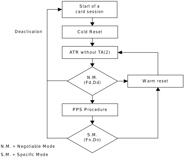
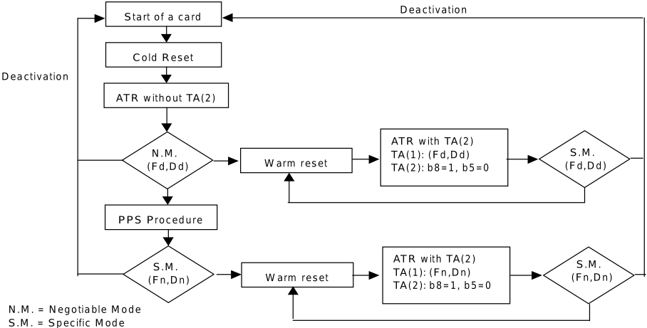
Annex J (informative): Example of the use of PINs
J.1 Application having several ADFs
From the security context point of view, 2 ADFs using the same application PIN are part of the same application. Each ADF then refers to the same local key reference number whose value and status is specific to each ADF. Figure J.1 illustrates it.
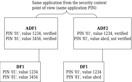
J.2 Two applications with two different security contexts
From the security context point of view, two applications use two different application PINs. Then the local PINs of the applications use two different key reference numbers, each one paired with its associated application PIN. Figure J.2 illustrates this scenario.
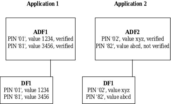
Annex K (informative):
Examples of the PIN state transition on multi verification capable UICC
K.0 Context
This annex describes two examples of the global PIN state transition on a multi verification capable UICC.
In figure K.1, following global PINs and ADFs are assigned in the UICC:
- the global PIN, key reference '01', is referred to as an application PIN of ADF A in SE (Security Environment) 01;
- the global PIN, key reference '02', is referred to as an application PIN of ADF B in SE 01;
- the global PIN, key reference '11', is referred to as an universal PIN of both ADFs in SE 00;
- any files under MF, highlighted area, can refer to global PINs.
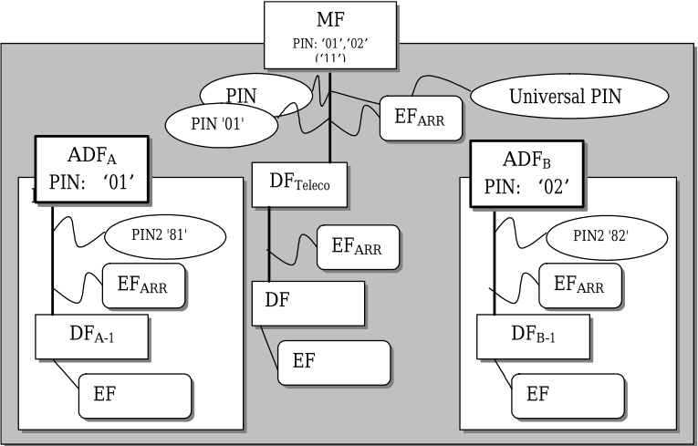
K.1 PIN state transition on the single logical channel
This clause describes global PIN state transition on a single-logical-channel scenario of the UICC illustrated in figure K.1.
The global PIN state transition contains:
- scenario on a logical channel;
- security status as PIN status and PIN verification state for PIN '11', '01' and '02';
- current ADF, DF and file;
- PIN status byte and usage qualifier for PIN '11' in PIN status DO;
- SE (Security Environment) ID.
| Logical channel #0 PIN status DO in the FCP | |||||||||||||||
|---|---|---|---|---|---|---|---|---|---|---|---|---|---|---|---|
| PIN status | status PIN verification state | Current | PIN status byte | Usage qualifier | SE ID | ||||||||||
| Scenario | channel #0 | PIN '11' | PIN '01' | PIN '02' | PIN '11' | PIN '01' | PIN '02' | ADF | DF | File | PIN '11' | PIN '01' | PIN '02' | PIN ('11') | |
| #1 | ATR | E | E | E | N | N | N | - | MF | MF | E | E | E | '00' | 01 |
| #2 | SELECT MF | ↓ | ↓ | ↓ | ↓ | ↓ | ↓ | - | ↓ | ↓ | ↓ | ↓ | ↓ | ↓ | ↓ |
| #3 | SELECT by DF-name (A) | ↓ | ↓ | ↓ | ↓ | ↓ | ↓ | ADF (A) | ADF (A) | ADF (A) | ↓ | ↓ | - | ↓ | ↓ |
| #4 | SELECT MF | ↓ | ↓ | ↓ | ↓ | ↓ | ↓ | ↓ | MF | MF | ↓ | ↓ | E | ↓ | ↓ |
| #5 | DISABLE PIN ('01' → '11') | ↓ | D (R) | ↓ | ↓ | V | ↓ | ↓ | ↓ | ↓ | ↓ | D | ↓ | '08' | 00 |
| #6 | VERIFY PIN ('11') | ↓ | ↓ | ↓ | V | ↓ | ↓ | ↓ | ↓ | ↓ | ↓ | ↓ | ↓ | ↓ | ↓ |
| #7 | SELECT ADF ('7FFF') | ↓ | ↓ | ↓ | ↓ | ↓ | ↓ | ↓ | ADF (A) | ADF (A) | ↓ | ↓ | - | ↓ | ↓ |
| #8 | SELECT by DF-name (B) | ↓ | ↓ | ↓ | ↓ | ↓ | ↓ | ADF (B) | ADF (B) | ADF (B) | ↓ | - | E | '00' | 01 |
| #9 | SELECT MF | ↓ | ↓ | ↓ | ↓ | ↓ | ↓ | ↓ | MF | MF | ↓ | D | ↓ | ↓ | ↓ |
| #10 | ATR | ↓ | ↓ | ↓ | N | ↓ | ↓ | - | ↓ | ↓ | ↓ | ↓ | ↓ | '08' | 00 |
| #11 | SELECT MF | ↓ | ↓ | ↓ | ↓ | ↓ | ↓ | - | ↓ | ↓ | ↓ | ↓ | ↓ | ↓ | ↓ |
| #12 | SELECT by DF-name (B) | ↓ | ↓ | ↓ | ↓ | ↓ | ↓ | ADF (B) | ADF (B) | ADF (B) | ↓ | - | ↓ | '00' | 01 |
| #13 | SELECT by DF-name (A) | ↓ | ↓ | ↓ | ↓ | ↓ | ↓ | ADF (A) | ADF (A) | ADF (A) | ↓ | D | - | '08' | 00 |
| NOTE: | -: None, ↓: same | status of | the | above, | V: Verified, | N: Not | verified, | E: | Enabled, | D: | Disabled, | R: | Replaced. | ||
K.2 PIN state transition between logical channels
This clause describes PIN state transition on a two-logical-channels scenario of the UICC illustrated in figure K.1.
The global PIN state transition contains:
- scenario between two logical channels;
- security status as PIN status and PIN verification state for PIN '11', '01' and '02';
- on each logical channel;
- current ADF, DF and file;
- PIN status byte and usage qualifier for PIN '11' in PIN status DO;
- SE (Security Environment) ID.
Logical channel #0 Logical channel #1 Security status Current PIN status DO in the FCP Current PIN status DO in the FCP Scenario PIN status PIN verification state PIN status byte Usage qualifier SE ID PIN status byte Usage qualifier SE ID channel #0 channel #1 PIN '11' PIN '01' PIN '02' PIN '11' PIN '01' PIN '02' ADF DF File PIN '11' PIN '01' PIN '02' PIN ('11') AD F DF File PIN '11' PIN '01' PIN '02' PIN ('11') #1 ATR E E E N N N - MF MF E E E '00' 01 #2 SELECT MF ↓ ↓ ↓ ↓ ↓ ↓ - ↓ ↓ ↓ ↓ ↓ ↓ ↓ #3 SELECT by DF-name (A) ↓ ↓ ↓ ↓ ↓ ↓ ADF (A) ADF (A) ADF (A) ↓ ↓ - ↓ ↓ #4 SELECT MF ↓ ↓ ↓ ↓ ↓ ↓ ↓ MF MF ↓ ↓ E ↓ ↓ #5 DISABLE PIN ('01' → '11') ↓ D (R) ↓ ↓ V ↓ ↓ ↓ ↓ ↓ D ↓ '08' 00 |
| PIN | Logical channel #0 status DO in | Logical channel #1 PIN status DO in the FCP | |||||||||||||||||||||
|---|---|---|---|---|---|---|---|---|---|---|---|---|---|---|---|---|---|---|---|---|---|---|---|
| Scenario | PIN | Security status | status PIN verification state | Current | PIN status byte | Usage qualifier SE ID | the FCP Current | PIN status byte qualifier | Usage | SE ID | |||||||||||||
| channel #0 | channel #1 PIN '11' | PIN '01' | PIN '02' | PIN '11' | PIN '01' | PIN '02' | ADF | DF | File | PIN '11' | PIN '01' | PIN PIN ('11') | AD F DF | File | PIN '11' | PIN '01' | PIN '02' | PIN ('11') | |||||
| #6 | VERIFY PIN ('11') | ↓ ↓ | ↓ | V | ↓ | ↓ | ↓ | ↓ | ↓ | ↓ | ↓ | '02' ↓ | ↓ | ↓ | |||||||||
| #7 | SELECT ADF ('7FFF') | ↓ ↓ | ↓ | ↓ | ↓ | ↓ | ↓ | ADF (A) | ADF (A) | ↓ | ↓ | - ↓ | ↓ | ||||||||||
| #8 | MANAGE CH. (#0 → #1) | ↓ ↓ | ↓ | ↓ | ↓ | ↓ | ↓ | ↓ | ↓ | ↓ | ↓ | - ↓ | ↓ | - | MF | MF | E | D | E | '08' | 00 | ||
| #9 | by | SELECT DF-name (B) ↓ | ↓ | ↓ | ↓ | ↓ | ↓ | ↓ ↓ | ↓ | ↓ | ↓ | - ↓ | ↓ | ADF (B) | ADF (B) | ADF (B) | ↓ | - | ↓ | '00' | 01 | ||
| #10 | SELECT MF ↓ | ↓ | ↓ | ↓ | ↓ | ↓ | ↓ | ↓ | ↓ | ↓ | ↓ | - ↓ | ↓ | ↓ | MF | MF ↓ | D | ↓ | ↓ | ↓ | |||
| #11 | ATR | ↓ ↓ | ↓ | N | ↓ | ↓ | - | MF | MF | ↓ | ↓ | E | ↓' | ↓ | |||||||||
| #12 | SELECT MF | ↓ ↓ | ↓ | ↓ | ↓ | ↓ | ↓ | ↓ | ↓ | ↓ | ↓ | ↓ ↓ | ↓ | ||||||||||
| #13 | SELECT by DF-name (B) | ↓ ↓ | ↓ | ↓ | ↓ | ↓ | ADF (B) | ADF (B) | ADF (B) | ↓ | - | ↓ | '00' | 01 | |||||||||
| #14 | MANAGE CH. (#0 → #1) | ↓ ↓ | ↓ | ↓ | ↓ | ↓ | ↓ | ↓ | ↓ | ↓ | - | ↓ | ↓ | ↓ | - | MF | MF | E D | E | '08' | 00 | ||
| #15 | by | SELECT DF-name (A) ↓ | ↓ | ↓ | ↓ | ↓ | ↓ | ↓ | ↓ | ↓ | ↓ | - | ↓ | ↓ | ↓ | ADF (A) | ADF (A) | ADF (A) ↓ | ↓ | - | ↓ | ↓ | |
| #16 | DISABLE PIN ('02') | ↓ ↓ | D | ↓ | ↓ | V | ↓ ↓ | ↓ | ↓ | - | D | ↓ | ↓ | ↓ | ↓ | ↓ | ↓ | ↓ - | ↓ | ↓ | |||
| #17 | SELECT ADF ('7FFF') | ↓ ↓ | ↓ | ↓ | ↓ | ↓ | ↓ ↓ | ↓ | ↓ | - | ↓ ↓ | ↓ | ↓ | ↓ | ↓ | ↓ ↓ | - | ↓ | ↓ | ||||
| Security status | Logical channel #0 PIN status DO | Logical in the FCP PIN | |||||||||||||||||||||
| Scenario | PIN status | PIN verification state | Current | PIN status | byte | Usage qualifier SE ID | Current | PIN status byte | the FCP Usage SE | ||||||||||||||
| channel #0 | channel #1 | PIN '11' | PIN '01' | PIN '02' | PIN '11' | PIN '01' | PIN '02' | ADF | DF | File PIN '11' | PIN '01' | PIN | '02' | PIN ('11') | AD F | DF | File | status PIN '11' | channel #1 DO in PIN '01' PIN '02' | qualifier PIN ('11') | ID | ||
| #18 | ENABLE PIN ('01) | ↓ E | ↓ | ↓ | ↓ | ↓ | ↓ | ↓ | ↓ ↓ | - | ↓ | ↓ | ↓ | ↓ | ↓ | ↓ | ↓ | E - | '00' | 01 | |||
| #19 | SELECT ADF ('7FFF') ↓ | ↓ | ↓ | ↓ | ↓ | ↓ | ↓ | ↓ | ↓ ↓ | - | ↓ | ↓ ↓ | ↓ | ↓ | ↓ | ↓ | ↓ - | ↓ | ↓ | ||||
| #20 | DISABLE PIN ('01' → '11') ↓ | D(R) | ↓ | ↓ | ↓ | ↓ | ↓ | ↓ | ↓ ↓ | - | ↓ | ↓ ↓ | ↓ | ↓ | ↓ | ↓ | D - | '08' | 00 | ||||
| #21 | SELECT ADF ('7FFF') | ↓ | ↓ ↓ | ↓ | ↓ | ↓ | ↓ | ↓ | ↓ ↓ | - | ↓ | ↓ | ↓ | ↓ | ↓ | ↓ | ↓ | ↓ - | ↓ | ↓ | |||
| #22 | ATR | ↓ | ↓ ↓ | ↓ | ↓ | ↓ | - | MF MF | ↓ | D | ↓ | ↓ ↓ | |||||||||||
| #23 | SELECT MF | ↓ | ↓ ↓ | ↓ | ↓ | ↓ | - | ↓ ↓ | ↓ | ↓ | ↓ | ↓ | ↓ | ||||||||||
| #24 | SELECT by DF-name (B) | ↓ | ↓ | ↓ | ↓ | ↓ | ↓ | ADF (B) | ADF (B) ADF (B) | ↓ | - | ↓ | ↓ | ↓ | |||||||||
| #25 | MANAGE CH. (#0 → #1) | ↓ | ↓ | ↓ | ↓ | ↓ | ↓ | ↓ | ↓ ↓ | ↓ | - | ↓ | ↓ | ↓ | - | MF | MF | E D | D | '00' | 01 | ||
| #26 | SELECT by DF-name (A) ↓ | ↓ | ↓ | ↓ | ↓ | ↓ | ↓ | ↓ ↓ | ↓ | - | ↓ | ↓ | ↓ | ADF (A) | ADF (A) | ADF (A) | ↓ | ↓ - | '08' | 00 | |||
| #27 | ENABLE PIN ('02') | ↓ | ↓ E | ↓ | ↓ | ↓ | ↓ | ↓ | ↓ | ↓ | - | E | ↓ | ↓ | ↓ | ↓ | ↓ | ↓ | ↓ - | ↓ | ↓ | ||
| #28 | DISABLE PIN ('02' → '11') | ↓ | ↓ D (R) | ↓ | ↓ | ↓ | ↓ | ↓ | ↓ ↓ | - | D | '08' | 00 | ↓ | ↓ | ↓ | ↓ ↓ | - | ↓ | ↓ | |||
| #29 | VERIFY PIN ('11') | ↓ | ↓ ↓ | V | ↓ | ↓ | ↓ | ↓ | ↓ ↓ | - | ↓ | ↓ | ↓ | ↓ | ↓ | ↓ | ↓ | ↓ - | ↓ | ↓ | |||
Logical channel #0 Logical channel #1 Security status Current PIN status DO in the FCP Current PIN status DO in the FCP Scenario PIN status PIN verification state PIN status byte Usage qualifier SE ID PIN status byte Usage qualifier SE ID channel #0 channel #1 PIN '11' PIN '01' PIN '02' PIN '11' PIN '01' PIN '02' ADF DF File PIN '11' PIN '01' PIN '02' PIN ('11') AD F DF File PIN '11' PIN '01' PIN '02' PIN ('11') #30 ATR ↓ ↓ ↓ N ↓ ↓ - MF MF ↓ D ↓ ↓ ↓ #31 SELECT MF ↓ ↓ ↓ ↓ ↓ ↓ - ↓ ↓ ↓ ↓ ↓ ↓ ↓ #32 SELECT by DF-name (B) ↓ ↓ ↓ ↓ ↓ ↓ ADF (B) ADF (B) ADF (B) ↓ - ↓ ↓ ↓ #33 MANAGE CH. (#0 → #1) ↓ ↓ ↓ ↓ ↓ ↓ ↓ ↓ ↓ ↓ - ↓ ↓ ↓ - MF MF E D D '08' 00 #34 SELECT by DF-name (A) ↓ ↓ ↓ ↓ ↓ ↓ ↓ ↓ ↓ ↓ - ↓ ↓ ↓ ADF (A) ADF (A) ADF (A) ↓ ↓ - ↓ ↓ NOTE: -: None, ↓: same status of the above, V: Verified, N: Not verified, E: Enabled, D: Disabled, R: Replaced. |
Annex L (informative):
Examples of SET DATA and RETRIEVE DATA usage
L.1 Examples of SET DATA and RETRIEVE DATA usage
This clause describes the sequences on APDU level, i.e. C-APDUs are given as:
CLA INS P1 P2 {Lc DATA} {Le}.
The presence of components enclosed in {…} depends on the case of the APDU.
The terminal stores some data in the object with tag 'A1' of length 45 kB with interruption, good case.
| Terminal | UICC | |
|---|---|---|
| SET DATA (First Block) | [80 DB 00 80 Lc A1 82 B4 00 xx … xx] | |
| 63 F1 | ||
| SET DATA (Next Block) | [80 DB 00 00 Lc xx … xx] | |
| 63 F1 | ||
| AUTHENTICATE | [00 88 00 XX Lc YY...YY Le | |
| [Data] 90 00 | ||
| SET DATA (Next Block) | [80 DB 00 00 Lc xx … xx] | |
| [01 D6 00 00 Lc xx … xx] | 63 F1 | |
| UPDATE BINARY on other logical channel | 90 00 | |
| SET DATA (Next Block) | [80 DB 00 00 Lc xx … xx] | |
| 63 F1 | ||
| ... | ... | ... |
| SET DATA (Next Block) | [80 DB 00 00 Lc xx … xx] | |
| 90 00 |
The terminal stores some data in the object with tag 'A1' of length 45 kB with interruption, error case.
| Terminal | UICC | |
|---|---|---|
| SET DATA (First Block) | [80 DB 00 80 Lc A1 82 B4 00 xx … xx] | |
| SET DATA (Next Block) | [80 DB 00 00 Lc xx … xx] | 63 F1 |
| AUTHENTICATE | 88 00 XX Lc YY...YY | 63 F1 |
| [00 Le] | [Data] 90 00 | |
| SET DATA (Next Block) | [80 DB 00 00 Lc xx … xx] | 63 F1 |
| UPDATE BINARY on same logical channel | [00 D6 81 00 Lc xx … xx] | 90 00 |
| SET DATA (Next Block) | [80 DB 00 00 Lc xx … xx] | |
| 6A 86 |
As a result of the error, the object with tag 'A1' is removed from the file.
The terminal retrieved the object with tag 'A2' with interruption (good case).
Table L.1.3: RETRIEVE DATA with interruption, good case
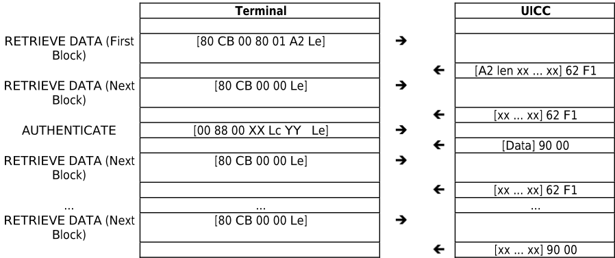
L.2 Examples of RETRIEVE DATA usage with transport protocol T = 0
This clause describes the sequences on APDU and TPDU level.
C-APDUs are given as:
CLA INS P1 P2 {Lc DATA} {Le}
C-TPDUs are given as:
CLA INS P1 P2 P3 {DATA}
The presence of components enclosed in {…} depends on the case of the APDU or the type of the TPDU.
This clause gives examples of the usage of the RETRIVE DATA command with transport protocol T = 0. The first example is based on the preconditions out of table L.1.3. Furthermore it is assumed that for the last block of the RETRIEVE DATA command only 64 additional data bytes are left to be retrieved to show the handling with the procedure byte '6C'. The second example shows the use of procedure byte '61' when a short object is retrieved.
| Terminal | UICC | |||
|---|---|---|---|---|
| RETRIEVE DATA (First Block) C-APDU: | [80 CB 00 80 01 A2 00] | |||
| C-TPDU: | [80 CB 00 80 01] | | ||
| [A2] (Tag) | | | [CB] (INS) 62 F1 (SW1/2: 'Warning: | |
| Get Response | [00 C0 00 00 00] | | | more data available') [C0] (INS) [A2 len xx ... xx] (256 Data |
| R-APDU: | [A2 len xx ... xx 62 F1] | bytes) + 90 00 (SW1/2 Normal ending of command) | ||
| RETRIEVE DATA (Next | [80 CB 00 00 00] | |||
| Block) C-APDU: C-TPDU: | [80 CB 00 00 00] | | | |
| R-APDU: | [xx ... xx 62 F1] | [CB] (INS) [xx ... xx] (256 Data bytes) + 62 F1 (SW1/2: 'more data available') | ||
| AUTHENTICATE C-APDU: C-TPDU: | [00 88 00 81 22 YY YY…YY 33] | |||
| [00 88 00 81 22] [YY YY…YY] (Data) | | | [88] (INS) | |
| Get Response | [00 C0 00 00 33] | | | 61 33 (SW1/2) [C0] (INS) [xx ... xx] (51 Data bytes) + |
| R-APDU: | [xx ... xx 90 00] | 90 00 (SW1/2) | ||
| RETRIEVE DATA (Next | [80 CB 00 00 00] | |||
| Block) C-APDU: C-TPDU: | [80 CB 00 00 00] | | | [CB] (INS) [xx ... xx] (256 Data bytes) + 62 F1 (SW1/2: 'more data available') |
| R-APDU: | [xx ... xx 62 F1] ... | ... | ||
| ... RETRIEVE DATA (Next Block) C-APDU: | [80 CB 00 00 00] (see note) | |||
| C-TPDU: | [80 CB 00 00 00] | | | 6C 40 (SW1/2: 'resend |
| previous command with P3 equal to '40' - 64 additional Data bytes available') | ||||
| [80 CB 00 00 40] | | |||
| [CB] (INS) [xx ... xx] (64 Data bytes) + 90 00 (all data retrieved) | ||||
| R-APDU: | [xx ... xx 90 00] |
NOTE: Terminals are usually expected to skip this step, because they can calculate the correct length of the last command from the length field of the data object. However, the UICC has to support the given procedure.
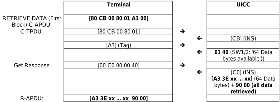
Annex M (informative):
Examples of ODD AUTHENTICATE instruction code usage
M.1 Examples of ODD AUTHENTICATE instruction code usage at applicative level
This clause describes the sequences on APDU level, i.e. C-APDUs are given as:
CLA INS P1 P2 {Lc DATA} {Le}
The presence of components enclosed in {…} depends on the case of the APDU.
The terminal sends some data in the object with tag '53' and the answer received by the UICC is in the object with tag '53'. The security context used in the example is P2='00'. The challenge data is [xx … xx] and the authentication response data is [yy … yy].
In the first example the length of the challenge data is 200 bytes ('C8' hex) and the length of the response data is 100 bytes ('64' hex).
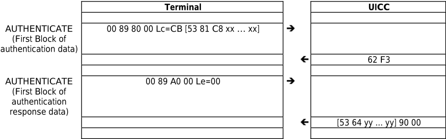
In the second example the length of the challenge data is 700 bytes ('02BC' hex) and the length of the response data is 600 bytes ('0258' hex).
| Terminal | UICC | |
|---|---|---|
| AUTHENTICATE (First Block of authentication data) | 00 89 80 00 Lc=FF [53 82 02 BC xx … xx] | |
| AUTHENTICATE (Next Block of authentication data) | 00 89 00 00 Lc=FF [xx … xx] | 63 F1 |
| AUTHENTICATE (Next Block of authentication data) | 00 89 00 00 Lc=C2 [xx … xx] | 63 F1 |
| AUTHENTICATE (First Block of authentication response data) | 00 89 A0 00 Le=00 | 62 F3 |
| AUTHENTICATE (Next Block of authentication response data) | 00 89 20 00 Le=00 | [53 82 02 58 yy ... yy] 62 F1 |
| AUTHENTICATE (Next Block of authentication response data) | 00 89 20 00 Le=5C | [yy ... yy] 62 F1 |
| [yy ... yy] 90 00 |
M.2 Examples of ODD AUTHENTICATE instruction code usage with transport protocol T = 0
This clause describes the sequences on APDU and TPDU level.
C-APDUs are given as:
CLA INS P1 P2 {Lc DATA} {Le}
C-TPDUs are given as:
CLA INS P1 P2 P3 {DATA}
The presence of components enclosed in {…} depends on the case of the APDU or the type of the TPDU.
This clause gives examples of the usage of the ODD AUTHENTICATE command usage with transport protocol T = 0. The first example is based on the preconditions out of table M.1.1. The second example is based on the preconditions out of table M.1.2.
| Terminal | UICC | |
|---|---|---|
| AUTHENTICATE (First Block of authentication data) C-APDU: | 00 89 80 00 Lc=CB [53 81 C8 xx … xx] | |
| C-TPDU: | [00 89 80 00 CB] | |
| [89] (INS) | ||
| [53 81 C8 xx … xx] (200 Data bytes) | 62 F3 (SW1/2: 'Warning: Authentication response data | |
| R-APDU: | [62 F3] | available') |
| AUTHENTICATE (First Block of authentication response data) C-APDU: | 00 89 A0 00 Le=00 | |
| C-TPDU: | [00 89 A0 00 00] | |
| 6C 66 (SW1/2: '66 bytes available') | ||
| [00 89 A0 00 66] | | |
| [53 64 yy ... yy] 90 00 | ||
| R-APDU: | [53 64 yy ... yy] [90 00] |
| Terminal | UICC | |
|---|---|---|
| AUTHENTICATE (First Block of authentication data) C-APDU: | 00 89 80 00 Lc=FF [53 82 02 BC xx … xx] | |
| C-TPDU: | [00 89 80 00 FF] | |
| [53 82 02 BC xx … xx] (251 Data bytes) | [89] (INS) | |
| 63 F1 (SW1/2: 'Warning: more data expected') | ||
| R-APDU: | [62 F1] | |
| AUTHENTICATE (Next Block of authentication data) C-APDU: | 00 89 00 00 Lc=FF [xx … xx] | |
| C-TPDU: | [00 89 00 00 FF] | |
| [xx … xx] (255 Data bytes) | [89] (INS) | |
| 63 F1 (SW1/2: 'Warning: more data expected') | ||
| R-APDU: | [63 F1] | |
| AUTHENTICATE (Next Block of authentication data) C-APDU: | 00 89 00 00 Lc=C2 [xx … xx] | |
| C-TPDU: | [00 89 00 00 C2] | [89] (INS) |
| [xx … xx] (194 Data bytes) | 62 F3 SW1/2: 'Warning: Authentication | |
| R-APDU: | [62 F3] | response data available') |
| AUTHENTICATE (First Block of authentication response data) C-APDU: | 00 89 A0 00 Le=00 | |
| C-TPDU: | [00 89 A0 00 00] | [89] (INS) [53 82 02 58 yy ... yy] 62 F1 |
| R-APDU: | [53 82 02 58 yy ... yy] [62 F1] (252 Data bytes) | |
| AUTHENTICATE (Next Block of authentication response data) C- APDU: | 00 89 20 00 Le=00 | |
| C-TPDU: | [00 89 20 00 00] | [89] (INS) [yy ... yy] 62 F1 |
| R-APDU: | [yy ... yy] [62 F1] (256 Data bytes) | |
| AUTHENTICATE (Next Block of authentication response data) C-APDU: | 00 89 20 00 Le=5C | |
| C-TPDU: | [00 89 20 00 5C] | [89] (INS) [yy ... yy] 90 00 |
| R-APDU: | [yy ... yy] [90 00] (92 Data bytes) |
Annex N (informative): Change history
The table below indicates all changes requests (CR) applied to the present document since it was created by TC SET (former TC SCP).
| Change history | |||||
|---|---|---|---|---|---|
| Date | Meeting SCP-02 | TC SCP Doc. 9-00-0289 | CR Rv - | Cat Subject/Comment Old - First draft created. Technical content is identical to | New 0.0.0 |
| 2000-08 | SCP-02 | 9-00-0342 | 001 | 3GPP TS 31.101 V3.2.0 F Correction and clarification of the provision of Contact C6 0.0.0 | 3.0.0 |
| 2000-08 | 9-00-0343 9-00-0307 | 002 003 | F Clarifications of Electrical characteristics F Clarification of the SELECT command with 'special' file-Ids F Clarification of GET RESPONSE command usage 3.0.0 | ||
| SCP-03 | 9-00-0454 9-00-0456 9-00-0459 9-00-0467 9-00-0451 9-00-0452 9-00-0453 9-00-0465 | 1 | UICC current consumption values for 3V and 1.8V for access conditions ATR example 'UICC characteristics byte' in FCP - TAG F Modification on using Proprietary information in FCP - TAG '81' F Support for minimum clock frequency indication to the terminal MF selection | ||
| 9-00-0293 9-00-0352 | 004 | release 4 F Correction to SFI values F Clarification of EFARR | |||
| 9-00-0375 9-00-0383 9-00-0385 9-00-0387 9-00-0391 9-00-0393 9-00-0394 | F Correction of T = 1 F Modification on using '80' | ||||
| 9-00-0346 | 005 | F ATR: Correction of Data Coding Byte DO F Correction to S-Block dependent errors and T = 1 ATR | |||
| 9-00-0348 | 006 | F Correction of the file descriptor information and PS Template example | |||
| 9-00-0359 | 007 008 | SELECT command response | |||
| 9-00-0364 | 009 | F F Clarifications and corrections to usage of SFI and reservation of file Ids | |||
| 9-00-0366 | 010 | F Clarification of access rules and ADF | |||
| 9-00-0367 | 011 | F Clarification of the location of EF(ARR) | |||
| 9-00-0368 | 012 | Clarifications to the SEARCH RECORD command | |||
| 9-00-0369 | 013 | F F Clarifications and corrections to clause 6 | |||
| 9-00-0373 | 014 | F Clarification to the INCREASE | |||
| 9-00-0374 | 015 | command F Clarifications and corrections transmission protocols in clause 7 | |||
| 016 | Clarification to VERIFY PIN | ||||
| 017 | F F Application selection using partial DF name | ||||
| 018 | F Correction of P1 of ACTIVATE and DEACTIVATE commands | ||||
| 019 | F Definition of SFIs | ||||
| 020 | F Collection of corrections and clarifications Support of TERMINAL PROFILE by an | ||||
| 021 | F UICC F Corrections to References and clarifications to | ||||
| 9-00-0396 | 022 023 | definitions F Correction of PIN related procedure in | |||
| 9-00-0397 9-00-0398 | 024 025 | F Clarifications and corrections to the security architecture clause 9 F Alignment of table for commands and status words | 4.0.0 | ||
| 2000-12 | 9-00-0463 | 026 | F Clarification to the requirement for the warm reset F Corrections and clarifications on multi-verification capable B Changing UICC | ||
| 2001-02 | 9-00-0466 SCP-010301 SCP-010303 | 027 028 | F Correction of implicit A Reservation of File ID '7F31' for iDEN Specifications 4.0.0 A Clarification of selection by path A Correction of the minimum pulse width during clock frequency switching A Clarification of the access rules referencing A Correction of EF(ARR) example in annex F A Clarification and correction regarding the Universal PIN F Clarification on Local PIN status | 4.1.0 4.3.0 | |
| 2001-10 | SCP-010210 SCP-010293 SCP-010295 SCP-010296 | 029 030 031 | A Clarification on block dependent errors A Location of local PIN | ||
| SCP-04 | 032 | Correction regarding Logical Channels | |||
| SCP-07 | 033 | Correction of definition of application and second | |||
| 034 | level Addition of an example on Access Rule | ||||
| SCP-05 | SCP-010041 SCP-010040 | 035 037 039 | |||
| 2001-04 | SCP-010054 SCP-010056 | 043 | 4.2.0 | ||
| 045 047 | 4.1.0 A B Addition of logical channels B Modification of security environment for logical channels | ||||
| SCP-010060 SCP-010062 | 049 | A Indication of amount of available memory A Clarification of selection by path (empty B Addition of GET CHALLENGE command | |||
| 2001-07 | 1 | ||||
| fields) Applicability of commands to applications | |||||
| SCP-010063 SCP-010121 SCP-010136 | C | ||||
| SCP-010133 | 050 | data | |||
| 051 | |||||
| SCP-010139 | 052 | Correction to total file size for DFs | |||
| SCP-010145 | 054 055 | ||||
| SCP-06 | SCP-010177 | 056 058 060 | 4.2.0 | 4.4.0 | |
| 064 066 | 4.3.0 | ||||
| 067 069 | application | ||||
| F A A | |||||
| 071 | referencing | ||||
| Date | Meeting | TC SCP Doc. | CR | Change history | Old | New |
|---|---|---|---|---|---|---|
| 2002-01 | SCP-08 | SCP-010290 | Rv 062 | Cat Subject/Comment A Clarification and correction regarding the Universal PIN and | 4.4.0 | 4.5.0 |
| SCP-010372 | 073 | Global PINs F | ||||
| SCP-010383 | 075 | Correction to status words for the MANAGE CHANNEL command A Inconsistency in the VERIFY PIN and UNBLOCK PIN commands | ||||
| definition Use of GET RESPONSE with case 2 and case 4 commands | ||||||
| 2002-03 | SCP-09 | SCP-010385 SCP-020041 | 076 078 | A F Correction of Errors in SELECT FILE by File Referencing Example | 4.5.0 | 5.0.0 |
| SCP-020043 | F Correct SELECT command parameter definitions | |||||
| SCP-020042 | 080 079 | C UICC presence detection procedure and usage modification | ||||
| 2002-06 | SCP-10 | SCP-020184 | 087 1 | F Correction to status words for the commands STATUS, ACTIVATE FILE, DEACTIVATE FILE, GET CHALLENGE and MANAGE CHANNEL | 5.0.0 | 5.1.0 |
| SCP-020158 | 084 090 | F Correction to Update Record F Correction of Procedure Byte '6Cxx' for case 2 commands with Le | ||||
| 093 | = '00' F SFI for EF(ICCID) and EF(ARR) F Additions to Abbreviations clause | |||||
| 081 | ||||||
| 2002-09 | SCP-11 | SCP-020210 | 096 | A Status word 6700 for Select command | 5.1.0 | 5.2.0 |
| SCP-020250 | 100 1 | A Corrections and clarifications to PIN handling | ||||
| SCP-020210 | 103 | F Clarification of default SE and default Usage Qualifier | ||||
| SCP-020253 | 106 | A Clarification of VERIFY PIN and UNBLOCK PIN | ||||
| 2003-01 | SCP-12 | SCP-030050 | 109 | F Introduction of the reference to the CAT specification F | 5.2.0 | 6.0.0 |
| SCP-030050 | 115 | Clarification of Proprietary Information field in FCP D | ||||
| SCP-030061 | 119 | Remove UICC as an abbreviation to align with 3GPP TR | ||||
| SCP-030059 | 112 1 | 21.905 F Corrections and clarifications | ||||
| SCP-030078 | 107 1 | D Refer to TLV Format Definitions in ETSI TS 101 220 (this CR created Rel-6) | ||||
| 2003-05 | SCP-13 | SCP-030111 | 120 | D Editorial Corrections on protocol definition | 6.0.0 | 6.1.0 |
| SCP-030111 SCP-030111 | 124 | F Clarification on use of '7FFF' for ADF selection F Delete special FID '3FFF' | ||||
| 2003-09 | SCP-14 | SCP-030293 | 131 132 1 | C Introduction of 85 °C instead of 70 °C as fully operational temperature | 6.1.0 | 6.2.0 |
| SCP-030296 | 133 | F | ||||
| 1 | Clarification of application session termination | |||||
| 2003-12 | SCP-15 | SCP-030411 SCP-030411 | 141 1 142 | B Introduction of a new Di factor on the card-terminal interface D | 6.2.0 | 6.3.0 |
| 140 | Informative annex on PIN state transition in multi verification | |||||
| SCP-030297 | 136 1 | C Semantics of the Shareable/Not-Shareable Bit | ||||
| SCP-030219 | F Correction of Security attributes length coding table | |||||
| 2004-02 | ||||||
| SCP-030411 | 144 | capable UICC Addition of the warning status SW1/SW2='6285' indicating the selected DF is in termination state | ||||
| B | ||||||
| SCP-030467 | 145 1 | D Correction to UICC status words | ||||
| SCP-16 | SCP-030485 SCP-040055 | 146 135 2 | A Extra turnaround time requirement for T = 0 B Introduction of a third card size for the UICC | 6.3.0 | 6.4.0 | |
| SCP-040032 SCP-040032 | 150 | F Clarification on the PPS procedure F Alignments regarding tag 86 | ||||
| 2004-05 | SCP-17 | SCP-040237 SCP-040237 | 151 155 156 | F Clarification of T = 0 description F Correction in the PIN state transition on the single logical channel | 6.4.0 | 6.5.0 |
| SCP-040237 | table (clause K.1) | |||||
| 157 | Clarification of status word '91xx' handling for Logical Channels | |||||
| F SELECT | ||||||
| SCP-040237 SCP-040237 | 159 160 | F Correction to UICC status words: Addition of 6985 for | ||||
| 2004-09 | SCP-18 | SCP-040316 | 161 | B Introduction of BER-TLV Efs (large files) | 6.6.0 | |
| 2004-11 | SCP-19 | SCP-040414 SCP-040414 | 162 | b Introduction of low impedance driver on the I/O line | 6.5.0 6.6.0 | 6.7.0 |
| 163 | F Clarification of sequence in PIN status template DO F Removing security attribute tag '86' as a possible tag within the | |||||
| SCP-040414 | 168 | FCP template Corrections to References and replacement of FCI with FCP | ||||
| 2004-11 2005-01 | SCP-19 | 177 1 | Correction of description of response data structure for T = 1 Delete status word '61XX' for T = 1 | 6.7.0 | 7.0.0 | |
| 173 | A | |||||
| SCP-040414 | A A | |||||
| SCP-050014 SCP-050014 | 180 | A Removing clause 8.5.5 on ETSI TS 102 221 A | ||||
| SCP-040474 SCPt040334 | 169 | C Clarification for response to SELECT | ||||
| SCP-20 | SCP-050014 SCP-050014 | 181 | Additional status word for commands capable to change the current file of a logical channel | 7.0.0 | 7.1.0 | |
| 187 | A Consistent usage of terms in SET DATA command | |||||
| 184 | Clarification of TLV object state in case of erroneous SET DATA | |||||
| A command | ||||||
| 2005-06 | SCP-21 | SCP-050014 SCP-050141 | 186 192 | A Additional status word for RETRIEVE and SET DATA A Correction on PIN verification status reset | 7.1.0 | 7.2.0 |
| SCP-050142 | 203 197 | A Add definition for "current file" F Modifications due to revision of ISO/IEC 7816 (all parts) | ||||
| Change history | ||||||
| Date 2005-09 | Meeting SCP-22 | TC SCP Doc. SCP-050227 | CR Rv 205 | Cat Subject/Comment A of the extra guard time after the last character in a | Old 7.2.0 | New |
| Removal command sent to the UICC | 7.3.0 | |||||
| SCP-050273 | 210 | Correction of ATR error handling | ||||
| SCP-050274 | 211 | A D Clarification for RETRIEVE DATA indicating 'First Block' | ||||
| 2005-12 | SCP-23 | SCP-050460 | 213 215 | A Correction to the use of 'allocated' in the SET DATA command Clarification on tag pointer changes for BER-TLV structured files | 7.3.0 | 7.4.0 |
| 217 | A A Clarification on 'File Size' for BER-TLV structured Efs | |||||
| SCP-050487 | 220 | A Coding of the first Tbi (i > 2) after T = 15 | ||||
| 2006-03 | SCP-25 | SCP-060140 | 222 | A Clarification of presence of PPS2 in PPS request | 7.4.0 | 7.5.0 |
| 2006-07 | SCP-26 | SCP-060244 SCP-060255 | 223 2 221 | B Addition of specific UICC environmental conditions D Clarification of annex L for RETRIEVE DATA with transport | 7.5.0 | 7.6.0 |
| protocol T = 0 | ||||||
| SCP-060282 | 222 218 | B Terminal capability indication mechanism B Corrections related to clarifications on TERMINATE Commands | ||||
| 2006-09 | SCP-27 | SCP-060441 | 225 | A Removal of retransmission of first block than what can | 7.6.0 | 7.7.0 |
| SCP-060467 | 228 1 | A Authenticate command with data message longer | ||||
| 226 1 | be transported in a single command Corrections to the Terminal Capabilities | |||||
| 2007-01 | SCP-29 | SCP-060465 SCP-070030 | 230 | F command D Addition of an annex on Authenticate command with data message longer than what can be transported in a single command | 7.7.0 | 7.8.0 |
| 231 | F Correction of incorrectly implemented CRs in REL-7 | |||||
| 3 | B | |||||
| 2007-04 | SCP-30 | SCP-070135 | 227 236 | Extension of the number of logical channels F CR to incorporate changes due to revision of ISO/IEC 7816-3. (Note that final change, clause 6.7, does not bear revision marks.) | 7.8.0 | 7.9.0 |
| 237 | Correction of editorial errors in protocol text | |||||
| D | ||||||
| 239 | A Authenticate command execution for ODD INS code | |||||
| 2007-05 | SCP- | SCP-070189 | 240 | B Addition of support for the Inter-Chip USB interface Addition of provisions for APDU usage over the IC USB interface | ||
| 2007-10 | 30bis SCP-33 | SCP-070422 | 241 242 | B B Addition of support for the UICC-CLF interface: - redefinition of contact C6 - inclusion of power consumption considerations | 7.9.0 | 7.10.0 |
| SCP-080016 | 243 | - indicators in ATR and Terminal Capabilities | 7.11.0 | |||
| 2008-05 | SCP-35 | D Correction of erroneous clause reference in clause 6.4 | 7.10.0 | |||
| 2008-05 | SCP-38 | SCP-080364 | 248 | B Addition of secure channel APDUs and indications | 7.11.0 | 7.12.0 |
| 2008-07 | SCP-38 | SCP-080358 | 245 1 | D Editorial Correction in clause C.1.7 | 7.12.0 | 8.0.0 |
| 2008-10 | SCP-39 | SCP-080460 | 250 2 | 8.0.0 | 8.1.0 | |
| 2008-10 | SCP-39 | SCP-080462 | A TRANSACT DATA command corrections | 8.0.0 | 8.1.0 | |
| 252 1 | A Corrections to MANAGE SECURE CHANNEL command | |||||
| 2009-01 | SCP-40 | SCP-090021 | 253 | C Clarification regarding local PIN assignment | 8.0.0 | 8.1.0 |
| ----- 2009-04 | --- SCP-41 | ---- SCP-090115 | 255 | A Rel-8 mirror of SCP-090076 created for v8.0.1 publication | 8.0.0 8.1.0 | 8.1.0 |
| 2009-04 | SCP-090138 | 257 | F Correction of 3GPP references definition | 8.1.0 | 8.2.0 | |
| SCP-41 | 259 | A Correction to clarify the secure channel container size and the indication of the algorithm and checksum | 8.2.0 | |||
| 2009-07 | SCP-42 | SCP-090258 | 261 1 | A Correction to ETSI TS 102 221 related to Secure Channel | 8.2.0 | 8.3.0 |
| 2009-10 | SCP-43 | SCP-090323 | 264 | A Optional status of the Secure channel | 8.3.0 | 8.4.0 |
| 2009-10 | SCP-43 | SCP-090323 | 267 | A Collection of corrections on Secure Channel | 8.3.0 | 8.4.0 |
| 2009-10 | SCP-090323 | 270 | A Correction on 'Abort Session' in secure channel | 8.3.0 | 8.4.0 | |
| 2009-10 | SCP-43 | SCP-090351 | 275 | Reservation of missing DF identifier (alignment with 3GPP | ||
| SCP-43 | A TS 31.102) | 8.3.0 | 8.4.0 | |||
| 2009-10 | SCP-43 | SCP-090323 | 262 | B Addition of AES 128 in Secure Channel | 8.3.0 | 9.0.0 9.0.0 |
| 2009-10 | SCP-43 | SCP-090346 | 1 | C Alignment of humidity class definition for UICC | 8.3.0 | |
| 2009-10 | SCP-43 | SCP-090348 | 265 272 | B Reservation of DF for 3GPP2 Multi-Mode System Selection | 8.3.0 | 9.0.0 |
| 2010-03 | SCP(10)0036 | (MMSS) D | 9.0.0 | |||
| 2010-03 | SCP-44 SCP-44 | 281 | Remove ambiguity in Start Secure Channel | 9.1.0 | ||
| 2010-07 | SCP-45 | SCP(10)0036 SCP(10)0175 | 285 1 | B EF LAUNCH PAD for SCWS access A | 9.0.0 | 9.1.0 |
| 2010-07 | SCP-45 | SCP(10)0166 | 290 291 2 | Behaviour for Manage Secure Channel - Terminate SA A Application selection on Application-to-application Secure | 9.1.0 | 9.2.0 |
| Channel | 9.1.0 | 9.2.0 | ||||
| 2010-10 | - | - | - - | - Correction of errors made during implementation of CR 161 and | 9.1.0 | 9.2.0 |
| CR 221 (ETSI Secretariat) | ||||||
| 2011-11 | SCP-46 SCP-46 | SCP(10)0293 SCP(10)0249 | 293 | C Security associations behaviour for A2A Secure Channel | 9.2.0 | 10.0.0 |
| 2011-11 | SCP(12)000007 | 294 | D Addition of organizations responsible for reserved DFs | 9.2.0 | 10.0.0 | |
| 2012-06 | SCP-55 | 295 | B Technical Specifications for the fourth UICC form factor | 11.0.0 | ||
| 2013-11 | SCP-57 | 297 1 | B Securing CAT communications | 10.0.0 11.0.0 | 11.1.0 | |
| 2014-02 | SCP-62 | SCP(12)000268r1 SCP(14)000032r1 | 298 | 12.0.0 | ||
| SCP-66 | SCP(14)000279 | 1 | B Reservation of EF ENV-CLASSES Identifier UICC start-up current modification | 11.1.0 11.1.0 | 12.0.0 | |
| 2014-12 2014-12 | SCP-66 | SCP(14)000274 | 299 300 | C UICC-ME interface execution timing requirement | 11.1.0 | 12.0.0 |
| SCP-66 | B B Addition of UICC increased idle current | |||||
| 2014-12 | SCP(14)000275 | 301 | 11.1.0 | 12.0.0 | ||
| 2015-02 | SCP-67 | SCP(15)000039 | 303 | A Corrections for responses for ENVELOPE commands | 12.0.0 | 12.1.0 |
| Change history | |||||||
|---|---|---|---|---|---|---|---|
| Date 2015-02 | Meeting SCP-67 | TC SCP Doc. SCP(15)000040 | CR 304 | Rv | Cat Subject/Comment C definition | Old 12.0.0 | New 12.1.0 |
| 2015-02 | SCP-67 | SCP(15)000041 | 305 | Performance improvement - Spike F Clarification on Terminal behaviour in case EFUMPC is not | 12.0.0 | 12.1.0 | |
| 2015-09 | - | - | - | - | present - To comply with ETSI drafting rules: - removal of hanging paragraphs through addition of clause headers where appropriate (source ETSI Secretariat + | 12.0.0 | 12.1.0 |
| 2015-04 | SCP-68 | SCP(15)000114r1 | 305 | Rapporteur) D | 12.1.0 | 13.0.0 | |
| 2015-04 | SCP-68 | SCP(15)000115 | 305 | Clarification on Voltage Classes Support D Correction of inconsistency with ISO/IEC 7816-4 selection | 12.1.0 | 13.0.0 | |
| 2015-07 | SCP-69 | SCP(15)000166 | 308 | mode C Changes for EF LAUNCH PAD to align with similar feature defined in USIM | 12.1.0 | 13.0.0 | |
| 2015-07 | SCP-69 | SCP(15)000167r1 | 309 | 1 | C Status Words for SEARCH RECORD no matches | 12.1.0 | 13.0.0 |
| 2015-12 | SCP-71 | SCP(15)000267 | 310 | B Terminal eUICC Capability indication | 13.0.0 | 13.1.0 | |
| 2015-12 | SCP-71 | SCP(15)000268 | 311 | B eUICC indication to terminal via ATR | 13.0.0 | 13.1.0 | |
| 2016-02 | SCP-72 | SCP(16)000015 | 312 | C | 13.0.0 | 13.1.0 | |
| 2016-10 | SCP -75 | SCP(16)000186 | 314 | GET RESPONSE after 6282 for SEARCH RECORD A Correction of reference to power negotiation section (implementation of CR 305) | 13.1.0 | 13.2.0 | |
| 2016-10 | SCP-75 | SCP(16)000185 | 313 | F Correction of reference to power negotiation section (implementation of CR 305) | 12.1.0 | 13.2.0 | |
| SCP-77 | SCP(17)000015r1 | 318 | 1 | PIN Status Data Object key references clarification | 13.1.0 | ||
| 2017-02 | SCP-77 | SCP(17)000016 | 315 | D | 13.2.0 | ||
| 2017-02 | 319 | F Envelope command return error code 69 82 | 13.1.0 | 13.2.0 | |||
| 2016-12 | SCP-76 | SCP(16)000228 | B UICC suspension mechanism B | 13.2.0 | 14.0.0 | ||
| 2017-02 | SCP-77 | SCP(17)000013r1 | 316 | 1 | Specification of the eUICC TLV in the TERMINAL CAPABILITY command | 13.2.0 | 14.0.0 |
| 2017-02 | SCP-77 | 317 | 1 | D Clarification of Key reference Value range | 13.2.0 | 14.0.0 | |
| 2018-02 | SCP-82 | SCP(17)000014r1 SCP(18)000017 | 324 | F Correction of table with commands and status words F | 14.0.0 14.0.0 | 14.1.0 14.1.0 | |
| 2018-02 | SCP-82 | SCP(18)000032r1 | 325 | 1 | Clarification of the presence of the SFI in the response to SELECT for an EF | 14.1.0 | |
| 2018-04 | SCP-83 | SCP(18)000089 | 322 | 2 | Clarification on the condition to switch voltage based on ATR | 14.0.0 | 14.1.0 |
| 2018-06 | SCP-84 SCP-84 | SCP(18)000179r1 | 327 | 1 | F F Suspend Resume Clarification | 14.0.0 | 14.1.0 |
| 2018-06 2017-09 | SCP-80 | SCP(19)000177r1 | 330 | 1 | F Replacement of Reference to ANSI X9.19: "MAC calculator" Clarification of the CLA byte in the GET RESPONSE command | 14.0.0 | |
| 2018-02 | SCP-82 | SCP(17)000128r1 SCP(18)000018 | 321 | 2 | Reserved DF under MF for the GSMA | 14.1.0 14.1.0 | 15.0.0 |
| 2018-02 | SCP-82 | SCP(18)000031r1 | 323 326 | 1 | D B D Alignment of Definitions and Abbreviations in SCP Specifications | 14.1.0 | 15.0.0 15.0.0 |
| 2018-06 | SCP-84 | SCP(18)000176r1 | 329 | 1 | B Addition of GET IDENTITY command | 14.1.0 | 15.0.0 |
| 2018-09 | SCP-85 | SCP(18)000235r1 | 331 | 1 | D editorial | 15.0.0 | |
| Correction of implementation problem of CR#327r1 and clean up after implementation of CR#299 | 15.1.0 | ||||||
| 2019-03 2019-03 | SCP-87 SCP-87 | SCP(19)000051 SCP(19)000052 | 332 333 | F Removal of reference to ISO/IEC 7811-3 F Alignment with ISO 7816-3:2006 | 15.1.0 15.1.0 15.1.0 | 15.2.0 15.2.0 | |
| 2019-03 2019-07 | SCP-87 SCP-88 | SCP(19)000053 | 334 336 | F Alignment of DEACTIVATE FILE with ETSI TS 102 222 | 15.2.0 | 15.2.0 15.3.0 | |
| 2019-07 | SCP(19)000114 | 337 | A Replacement of reference to ETSI TS 103 383 | 15.3.0 | 16.0.0 | ||
| 2019-10 | SCP-88 | SCP(19)000115 | C Support of the universal PIN | 16.0.0 | |||
| 2020-04 | SCP-89 | SCP(19)000170 | 339 | A Addition of EXCHANGE CAPABILITIES INS | 16.1.0 | ||
| SCP-91 SCP-95 | SCP(20)091029r1 | 341 342 | 1 1 | A Clarification of Exchange Capability command for UICC Clarification of the scope of the UICC status of the | 16.1.0 16.2.0 | 16.2.0 16.3.0 | |
| 2020-09 | SCP(20)000103r1 | D SUSPEND UICC command | |||||
| 2020-11 2021-01 | SCP-96 | SCP(20)000111r1 | 343 | 1 | C SET DATA command clarification for retransmit previous block TERMINAL CAPABILITY TLV for SGP.22 | 16.2.0 16.3.0 | 16.3.0 16.4.0 |
| 2021-04 | SCP-98 SCP-99 | SCP(21)000011 SCP(21)000041 | 344 345 | Clarification of data object transfer RETRIEVE DATA with tag 5C | 16.3.0 | 16.4.0 | |
| C D | 16.4.0 | ||||||
| 2021-07 | SCP-100 | SCP(21)000072 | 346 | D | 16.5.0 | ||
| 2021-07 | SCP-100 | 347 | 1 | Clarify applicability of table 10.5 F Update of Reference to JEDEC JESD22 and editorial | 16.4.0 | 16.5.0 | |
| SCP(21)000071r1 | improvements D | 16.5.0 | |||||
| 2021-09 2021-09 | SCP-101 SCP-101 | SCP(21)000135 SCP(21)000134 | 348 349 | Details on INS collisions F Editorial improvements | 16.5.0 | 16.6.0 16.6.0 | |
| 2021-09 | SCP-101 | SCP(21)000136 | 350 | B Introduction of the voltage class D for UICC to support 1,2 V operating conditions | 16.6.0 | 17.0.0 | |
| 1 | F Updates of terms and definitions related to voltage Removal of inconsistency about the supported form factors for the terminal | 17.0.0 17.0.0 | |||||
| 2021-12 | SCP-103 | SCP(21)000211 | 351 | operating conditions | 17.1.0 | ||
| 2022-03 | SCP-103 | SCP(21)000212r1 | 352 | F Clarification of ATR bytes for T=1 | 17.1.0 | 17.1.0 | |
| 2021-12 | SET-104 | SET(22)000037 SET(22)000103r1 | 353 354 | D | 17.2.0 | ||
| 2022-07 | SET-106 | Support of 32 LSIs in T=1 compliant ISO7816-3 | 17.1.0 | 17.2.0 | |||
| B | |||||||
History
| Document history | ||
|---|---|---|
| V17.0.0 | October 2021 | Publication |
| V17.1.0 | February 2022 | Publication |
| V17.2.0 | August 2022 | Publication |
Intellectual Property Rights
Essential patents
IPRs essential or potentially essential to normative deliverables may have been declared to ETSI. The declarations pertaining to these essential IPRs, if any, are publicly available for ETSI members and non-members, and can be found in ETSI SR 000 314: "Intellectual Property Rights (IPRs); Essential, or potentially Essential, IPRs notified to ETSI in respect of ETSI standards", which is available from the ETSI Secretariat. Latest updates are available on the ETSI Web server (https://ipr.etsi.org/).
Pursuant to the ETSI Directives including the ETSI IPR Policy, no investigation regarding the essentiality of IPRs, including IPR searches, has been carried out by ETSI. No guarantee can be given as to the existence of other IPRs not referenced in ETSI SR 000 314 (or the updates on the ETSI Web server) which are, or may be, or may become, essential to the present document.
Trademarks
The present document may include trademarks and/or tradenames which are asserted and/or registered by their owners. ETSI claims no ownership of these except for any which are indicated as being the property of ETSI, and conveys no right to use or reproduce any trademark and/or tradename. Mention of those trademarks in the present document does not constitute an endorsement by ETSI of products, services or organizations associated with those trademarks.
DECT™, PLUGTESTS™, UMTS™ and the ETSI logo are trademarks of ETSI registered for the benefit of its Members. 3GPP™ and LTE™ are trademarks of ETSI registered for the benefit of its Members and of the 3GPP Organizational Partners. oneM2M™ logo is a trademark of ETSI registered for the benefit of its Members and of the oneM2M Partners. GSM ® and the GSM logo are trademarks registered and owned by the GSM Association.
© European Telecommunications Standards Institute. Converted automatically from the published PDF; layout, figures and tables may differ from the original. The authoritative version is the original: https://www.etsi.org/deliver/etsi_ts/102200_102299/102221/17.02.00_60/ts_102221v170200p.pdf.