Test Tolerances Methodology for Inter-system Handover from UTRAN TDD to E-UTRAN: Unknown Target Cell
Specification: 34.122 8.3.3c+8.3.3d TT
Summary
This document describes the process to derive the Test Tolerances for Inter-system Handover from UTRAN TDD to E-UTRAN: Unknown Target Cell test cases 8.3.3c and 8.3.3d in TS 34.122.
Specification Intelligence
This is a Test Tolerance Document for UE Conformance Testing specification 34.122, specifically covering test case 8.3.3. The document is currently in immature draft.
Classification
Specifics
Version
Full Document v000
Title: Test Tolerances Methodology for Inter-system Handover from UTRAN TDD to E-UTRAN: Unknown Target Cell
Source: Rohde & Schwarz
Document for: Agreement
1. Introduction
This discussion paper relates to the Inter-system Handover from UTRAN TDD to E-UTRAN : Unknown Target Cell test cases 8.3.3c and 8.3.3d in TS 34.122. The test cases are:
8.3.3c Inter-system Handover from UTRAN TDD to E-UTRAN FDD: Unknown Target Cell
8.3.3d Inter-system Handover from UTRAN TDD to E-UTRAN TDD; Unknown Target Cell
This document describes the process to derive the Test Tolerances. The calculations are provided in the accompanying spreadsheet.
2. Test cases in TS 25.123
The test conditions are defined in the following extracts from TS 25.123 v10.4.0. Only 1.28Mcps option is provided.
A.5.3d.1.2 1.28 Mcps TDD option
This test is to verify the requirement for UTRAN TDD to E-UTRAN TDD handover requirements specified in section 5.3b when the target E-UTRAN cell is unknown.
The test scenario comprises of 1 UTRA TDD cell and 1 E-UTRA FDD cell as given in tables A.5.3c.1.2-1, A.5.3c.1.2-2, and A.5.3c.1.2-3. No scheduled idle interval is configured in the test case.
The test consists of two successive time periods, with time durations of T1 and T2 respectively. During time duration T1, a RRC HANDOVER FROM UTRAN COMMAND message shall be sent to the UE with activation time "now" with a new active E-UTRA FDD cell, cell2. The end of the last TTI containing handover message is the beginning of T2 duration. At the start of time duration T2, the UE does not have any timing information of Cell 2.
Table A.5.3c.1.2-1: General test parameters for UTRA TDD to unknown E-UTRA FDD handover test case
Parameter |
Unit |
Value |
Comment |
|
DPCH parameters active cell |
|
DL Reference Measurement Channel 12.2 kbps |
As specified in TS 25.102 section A. The DPCH is located in an other timeslot than 0. |
|
PDSCH parameters |
|
DL Reference Measurement Channel R.0 FDD |
As specified in TS 36.133 section A.3.1.1.1 |
|
PCFICH/PDCCH/PHICH parameters |
|
DL Reference Measurement Channel R.6 FDD |
As specified in TS 36.133 section A.3.1.2.1 |
|
Initial conditions |
Active cell |
|
Cell 1 |
UTRA 1.28Mcps TDD cell |
Neighbour cell |
|
Cell 2 |
E-UTRA FDD cell |
|
Final conditions |
Active cell |
|
Cell 2 |
E-UTRA FDD cell |
CP length of cell 2 |
|
Normal |
|
|
PRACH configuration |
|
4 |
As specified in table 5.7.1-2 in 3GPP TS 36.211 |
|
Handover activation time |
|
Now |
|
|
Access Barring Information |
|
Not Sent |
No additional delays in random access procedure. |
|
TimeToTrigger |
ms |
0 |
|
|
Filter coefficient |
|
0 |
L3 filtering is not used |
|
Hysteresis |
dB |
0 |
|
|
T1 |
s |
5 |
During T1, cell 2 shall be powered off, and during the off time the physical layer cell identity shall be changed. |
|
T2 |
s |
1 |
|
|
Table A.5.3c.1.2-2: Cell specific test parameters for UTRA TDD to unknown E-UTRA FDD handover test case (cell 1)
Parameter |
Unit |
Cell 1 (UTRA) |
|||
Timeslot Number |
|
0 |
DwPTS |
||
|
|
T1 |
T2 |
T1 |
T2 |
UTRA RF Channel Number* |
|
Channel 1 |
|||
PCCPCH_Ec/Ior |
dB |
-3 |
|
||
DwPCH_Ec/Ior |
dB |
|
0 |
||
OCNS_Ec/Ior |
dB |
-3 |
|
||
|
dB |
4 |
4 |
4 |
4 |
|
dBm/1.28 MHz |
-80 |
|||
PCCPCH RSCP |
dBm |
-79 |
-79 |
n.a. |
|
Propagation Condition |
|
AWGN |
|||
* Note: In the case of multi-frequency cell, the UTRA RF Channel Number is the primary frequency’s channel number. |
|||||
Table A.5.3c.1.2-3: Cell specific test parameters for UTRA TDD to unknown E-UTRA FDD handover test case (cell 2)
Parameter |
Unit |
Cell 2 |
|
T1 |
T2 |
||
E-UTRA RF Channel Number |
|
2 |
|
BWchannel |
MHz |
10 |
|
OCNG Patterns defined in TS36.133 A.3.2.1.1 (OP.1 FDD) and in A.3.2.1.2 (OP.2 FDD) |
|
OP.2 FDD |
OP.1 FDD |
PBCH_RA |
dB |
0 |
0 |
PBCH_RB |
dB |
||
PSS_RB |
dB |
||
SSS_RB |
dB |
||
PCFICH_PA |
dB |
||
PHICH_PA |
dB |
||
PHICH_PB |
dB |
||
PDCCH_PA |
dB |
||
PDCCH_PB |
dB |
||
PDSCH_PA |
dB |
||
PDSCH_PB |
dB |
||
OCNG_RANote1 |
dB |
||
OCNG_RBNote1 |
dB |
||
|
dB |
-Infinity |
0 |
|
dBm/15kHz |
-98 |
|
|
dB |
-Infinity |
0 |
RSRP |
dBm/15kHz |
-Infinity |
-98 |
SCH_RP |
dBm/15kHz |
-Infinity |
-98 |
Propagation Condition |
|
AWGN |
|
Note 1: OCNG shall be used such that cell is fully allocated and a constant total transmitted power spectral density is achieved for all OFDM symbols. Note 2: RSRP levels have been derived from other parameters for information purposes. They are not settable parameters themselves. |
|||
-------------------TEXT SKIPPED----------------------------
A.5.3d.1.2 1.28 Mcps TDD option
This test is to verify the requirement for UTRAN TDD to E-UTRAN TDD handover requirements specified in section 5.3b when the target E-UTRAN cell is unknown.
The test scenario comprises of 1 UTRA TDD cell and 1 E-UTRA TDD cell as given in tables A.5.3d.1.2-1, A.5.3d.1.2-2, and A.5.3d.1.2-3. No scheduled idle interval is configured in the test case.
The test consists of two successive time periods, with time durations of T1 and T2 respectively. During time duration T1, a RRC HANDOVER FROM UTRAN COMMAND message shall be sent to the UE with activation time "now" with a new active E-UTRA TDD cell, cell2. The end of the last TTI containing handover message is the beginning of T2 duration. At the start of time duration T2, the UE does not have any timing information of Cell 2.
Table A.5.3d.1.2-1: General test parameters for UTRA TDD to unknown E-UTRA TDD handover test case
Parameter |
Unit |
Value |
Comment |
|
DPCH parameters active cell |
|
DL Reference Measurement Channel 12.2 kbps |
As specified in TS 25.102 section A. The DPCH is located in an other timeslot than 0. |
|
PDSCH parameters |
|
DL Reference Measurement Channel R.0 TDD |
As specified in section A.3.1.1.2 in [24] |
|
PCFICH/PDCCH/PHICH parameters |
|
DL Reference Measurement Channel R.6 TDD |
As specified in section A.3.1.2.2 in [24] |
|
Initial conditions |
Active cell |
|
Cell 1 |
UTRA 1.28Mcps TDD cell |
Neighbour cell |
|
Cell 2 |
E-UTRA TDD cell |
|
Final conditions |
Active cell |
|
Cell 2 |
E-UTRA TDD cell |
CP length of cell 2 |
|
Normal |
|
|
Uplink-downlink configuration |
|
1 |
As specified in table 4.2-2 in 3GPP TS 36.211 |
|
Special subframe configuration |
|
6 |
As specified in table 4.2-1 in 3GPP TS 36.211 |
|
PRACH configuration |
|
53 |
As specified in table 5.7.1-3 in 3GPP TS 36.211 |
|
Handover activation time |
|
now |
|
|
Access Barring Information |
|
Not Sent |
No additional delays in random access procedure. |
|
TimeToTrigger |
ms |
0 |
|
|
Filter coefficient |
|
0 |
L3 filtering is not used |
|
Hysteresis |
dB |
0 |
|
|
T1 |
s |
5 |
During T1, cell 2 shall be powered off, and during the off time the physical layer cell identity shall be changed. |
|
T2 |
s |
1 |
|
|
Table A.5.3d.1.2-2: Cell specific test parameters for UTRA TDD to unknown E-UTRA TDD handover test case (cell 1)
Parameter |
Unit |
Cell 1 (UTRA) |
|||
Timeslot Number |
|
0 |
DwPTS |
||
|
|
T1 |
T2 |
T1 |
T2 |
UTRA RF Channel Number* |
|
Channel 1 |
|||
PCCPCH_Ec/Ior |
dB |
-3 |
|
||
DwPCH_Ec/Ior |
dB |
|
0 |
||
OCNS_Ec/Ior |
dB |
-3 |
|
||
|
dB |
4 |
4 |
4 |
4 |
|
dBm/1.28 MHz |
-80 |
|||
PCCPCH RSCP |
dBm |
-79 |
-79 |
n.a. |
|
Propagation Condition |
|
AWGN |
|||
* Note: In the case of multi-frequency cell, the UTRA RF Channel Number is the primary frequency’s channel number. |
|||||
Table A.5.3d.1.2-3: Cell specific test parameters for UTRA TDD to unknown E-UTRA TDD handover test case (cell 2)
Parameter |
Unit |
Cell 2 |
|
T1 |
T2 |
||
E-UTRA RF Channel Number |
|
2 |
|
BWchannel |
MHz |
10 |
|
OCNG Patterns defined in TS36.133 A.3.2.2.1 (OP.1 TDD) and in A.3.2.2.2 (OP.2 TDD) |
|
OP.2 TDD |
OP.1 TDD |
PBCH_RA |
dB |
0 |
0 |
PBCH_RB |
dB |
||
PSS_RB |
dB |
||
SSS_RB |
dB |
||
PCFICH_PA |
dB |
||
PHICH_PA |
dB |
||
PHICH_PB |
dB |
||
PDCCH_PA |
dB |
||
PDCCH_PB |
dB |
||
PDSCH_PA |
dB |
||
PDSCH_PB |
dB |
||
OCNG_RANote1 |
dB |
||
OCNG_RBNote1 |
dB |
||
|
dB |
-Infinity |
0 |
|
dBm/15kHz |
-98 |
|
|
dB |
-Infinity |
0 |
RSRP |
dBm/15kHz |
-Infinity |
-98 |
SCH_RP |
dBm/15kHz |
-Infinity |
-98 |
Propagation Condition |
|
AWGN |
|
Note 1: OCNG shall be used such that cell is fully allocated and a constant total transmitted power spectral density is achieved for all OFDM symbols. Note 2: RSRP levels have been derived from other parameters for information purposes. They are not settable parameters themselves. |
|||
We note that the level and time parameters for FDD and TDD respectively in tables A.5.3c.1.2-2 and A.5.3d.1.2-2, tables A.5.3c.1.2-3 and A.5.3d.1.2-3 are identical, so the same treatment for Test Tolerances can be applied for both Test cases.
3. Discussion
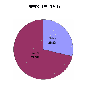
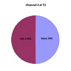
The test case has 2 time periods: T1 and T2. To analyse the test case it is helpful to visualise these as pie-charts, showing the distribution of power, as below:
Channel 1 (UTRAN TDD)
Channel 2 (E-UTRAN FDD)
3.1 Observations
Channel 1 is unchanged during T1, T2. Cell 1 PCCPCH_Ec/Io is -4.46dB and Ior/Ioc is 4 dB.
For Channel 2, Cell 2 only exist during T2, Cell 2 RSRP is -98dBm
During T2 Cell 2 (E-UTRAN FDD), the UE shall be ready to transmit on the channel of the new RAT.
4. Choice and values of uncertainties to be specified
The SS provides 2 cells on different frequencies, each with AWGN. We propose to control the following parameters:
For cell 1 (UTRA TDD):
Absolute level uncertainty of Ioc : +/-0.7dB
Ratio of cell 1 DwPCH_Ec/ signal ,DwPCH_Ec /Ior ±0.1 dB
The absolute level of Ioc is specified as ±0.7dB as in similar RRM test cases.
For cell 2 (E-UTRA FDD):
AWGN absolute power on cell 2 frequency, Noc uncertainty : ±0.7 dB
Ratio of cell 2 signal / AWGN, Ês / Noc uncertainty :±0.3 dB
The absolute level of Noc directly affects the UE’s RSRP measurement, and is specified as ±0.7 dB as in similar RRM test cases.
5. Calculation of Test Tolerances
General approach
The general approach is given in the steps below:
Copy the originally specified key parameters from the core requirements
Where relevant, calculate derived parameters from the core requirements
Define uncertainties for a minimum set of parameters
Define controlled parameters (critical to the test verdict), calculate sensitivity factors and uncertainty
Determine which original or derived parameters to offset (apply Test Tolerances to) and by how much
Recalculate original or derived parameters including Test Tolerances
Check that the controlled parameters meet requirements to get the correct test verdict
Each step is explained below, and the calculations are given in the accompanying spreadsheet.
a) Original specified key parameters
The key parameters need to be copied from Table A.5.3c.1.2-2 and A.5.3c.1.2-3 in TS 25.123 v10.4.0. The key parameters are selected as the minimum set to define the cell power levels, and which are subject to a test system uncertainty which may affect the verdict of the test.
b) Derived parameters
A number of derived parameters are calculated, using the base information in a). The reason for deriving each additional parameter is given in the “Comment” column of section b) in the accompanying spreadsheet.
In this test case during T2, for Cell 2 RSRP measurement to be valid, Es/Iot, RSRP and Io need to be checked.
c) Uncertainties
The choice of Test system uncertainties is covered in section 4 of this document. They appear in section c) in the accompanying spreadsheet.
d) Controlled parameters critical to verdict
From TS TS 25.123 clause A.5.3c, Cell 2 does not exist during T1.
During T1 the UE is required to detect Cell 1, which is the only defined cell present. Cell 1 must meet the PCCPCH RSCP side conditions from 25.123 clause 9.1.1.1.1.2.
9.1.1.1.1.2 1.28 Mcps TDD option
The accuracy requirements in table 9.1A are valid under the following conditions:
P-CCPCH RSCP -102 dBm
P-CCPCH Ec/Io > -8 dB
DwPCH_Ec/Io > -5 dB
Table 9.1A: P-CCPCH_RSCP absolute accuracy
Parameter |
Unit |
Accuracy [dB] |
Conditions |
|
Normal condition |
Extreme condition |
Io [dBm/ 1.28 MHz] |
||
P-CCPCH_RSCP |
dBm |
6 |
9 |
-94...-70 |
dBm |
8 |
11 |
-70...-50 |
|
During T2 the UE is required to handover to E-UTRA Cell 2. The conditions for the handover are:
Cell 2 must meet RSRP, Es/Iot and Io conditions for the RSRP measurement to be valid. Such conditions are specified in TS 34.122 clause 8.7.14 and clause 8.7.15
In Cell DCH state, whether or not UE requires idle intervals to perform E-UTRAN measurements, the requirements for accuracy of E-UTRA RSRP measurements in CELL_DCH state shall be the same as the inter-frequency RSRP Accuracy Requirements in 3GPP TS 36.133, as follows:
Cell specific reference signals are transmitted either from one, two or four antenna ports.
Conditions defined in 36.101 Section 7.3 for reference sensitivity are fulfilled.
RSRP|dBm -127 dBm for Bands 1, 4, 6, 10, 18, 19, 33, 34, 35, 36, 37, 38, 39, 40,
RSRP|dBm -126 dBm for Bands 9,
RSRP|dBm -125 dBm for Bands 2, 5, 7, 11, 17,
RSRP|dBm -124 dBm for Bands 3, 8, 12, 13, 14
Table 8.7.14.2-1: RSRP Inter frequency absolute accuracy
Parameter |
Unit |
Accuracy [dB] |
Conditions1 |
||||
Normal condition |
Extreme condition |
Bands 1, 4, 6, 10, 18, 19, 33, 34, 35, 36, 37, 38, 39, 40 |
Bands 2, 5, 7, 11, 17 |
Bands 3, 8, 12, 13, 14 |
Band 9 |
||
Io |
Io |
Io |
Io |
||||
RSRP for Ês/Iot -6 dB |
dBm |
6 |
9 |
-121dBm/15kHz … -70dBm/ BWChannel |
-119dBm/15kHz … -70dBm/ BWChannel |
-118dBm/15kHz … -70dBm/ BWChannel |
-120dBm/15kHz … -70dBm/ BWChannel |
RSRP for Ês/Iot -6 dB |
dBm |
8 |
11 |
-70dBm/ BWChannel … -50dBm/ BWChannel |
-70dBm/ BWChannel … -50dBm/ BWChannel |
-70dBm/ BWChannel … -50dBm/ BWChannel |
-70dBm/ BWChannel … -50dBm/ BWChannel |
Note 1: Io is assumed to have constant EPRE across the bandwidth. |
|||||||
The E-UTRA Cell 2 must be detectable, as specified in TS 25.123 clause 8.1.2.7 and clause 8.1.2.8:
An E-UTRAN cell shall be considered detectable when
- RSRP|dBm and RSRP Ês/Iot, according to Annex B.2.1 for a corresponding Band
- Other RSRP related side condition given in Section 9.1 of [24] are fulfilled for a corresponding Band,
- SCH_RP|dBm and SCH_Ês/Iot, according to Annex B.2.1 for a corresponding Band
B.2.1. Conditions for identification of a new cell in CELL_DCH State (3.84 Mcps option)
This section defines the E-UTRAN RSRP, RSRP Ês/Iot, SCH_RP and SCH Ês/Iot applicable for a corresponding operating band.
The conditions for identification of a new cell in CELL_DCH State (3.84 Mcps option) are defined in Table B.2.1-1
Table B.2.1-1. Conditions for identification of a new cell in CELL_DCH State
Parameter |
Conditions |
|||
Bands |
Bands |
Bands
|
Bands
|
|
1, 4, 6, 10, 11, 33, 34, 35, 36, 37, 38, 39, 40 |
9 |
2, 5, 7 |
3, 8, 12, 13, 14, 17 |
|
RSRP|dBm |
-125 dBm |
-124 dBm |
-123 dBm |
-122 dBm |
SCH_RP|dBm |
-125 dBm |
-124 dBm |
-123 dBm |
-122 dBm |
RSRP Ês/Iot |
-4 dB |
|||
SCH Ês/Iot |
-4 dB |
|||
B.2.2. Conditions for identification of a new cell in CELL_DCH State (1.28 Mcps option)
This section defines the E-UTRAN RSRP, RSRP Ês/Iot, SCH_RP and SCH Ês/Iot applicable for a corresponding operating band.
The conditions for identification of a new cell in CELL_DCH State (1.28 Mcps option) are defined in Table B.2.1-1
In many RRM test cases, and particularly multi-cell tests, there is not a simple one-to-one relationship between the parameters that can be set by the test equipment, and their effect on parameters determining the test verdict.
It is therefore essential to identify those parameters determining the test verdict. The 7 controlled parameters listed in the accompanying spreadsheet have been derived by study of the test case and by careful reading of the relevant clauses in TS 25.123 and TS 36.133. The reason for each parameter being critical to the test verdict is given briefly in the “Comment” column of section d) in the accompanying spreadsheet. Information about the value to be achieved is given later in the “Comment” column of section g) in the spreadsheet.
In general all the values are listed for each time interval T1, T2 for channel 1, but as cell 2 is not present during T1, then cell 2 values are only calculated in time interval T2.
Having identified the parameters critical to the test verdict which need to be controlled, we now need to consider how they are affected by the parameters which can be set by the test equipment. This is done by working out “sensitivity factors”. A sensitivity factor is just the ratio (effect on a critical parameter y / a test equipment uncertainty x), and is usually in dB/dB. In this RRM test case there is usually a simple one-to-one relationship between the parameters that can be set by the test equipment, and their effect on parameters determining the test verdict. The sensitivity factors are therefore derived by inspection as one or zero.
For example, for channel 2, an error of 1dB in the absolute AWGN level Noc would cause 1dB error in the Cell 2 RSRP, so the sensitivity factor is 1.000 during T2. However the same error of 1dB in the absolute AWGN level Noc would cause no change to Cell 2 Es/Iot, because all other powers are specified relative to Noc, so the sensitivity factor is zero.
The overall cell power Io is an exception, as the effect of Es/Noc uncertainty is diluted depending on the linear fraction of cell power making up the total. The sensitivity factor is made equal to the linear fraction of cell power on that frequency.
Having filled in the matrix of sensitivity factors, the accompanying spreadsheet calculates the overall uncertainty for each controlled parameter, taking into account the uncertainties and sensitivity factors for each parameter that can be set by the test equipment. This process follows the superposition principle. More details and explanation can be found in section 4 of TS 36.903. Uncertainties are calculated separately for T1, T2.
For the test system uncertainties the normal procedure of combining uncorrelated uncertainties root-sum-square is followed.
e) Determine parameters to offset
During T1 the UE is required to select to Cell 1, which is the only defined cell present. For UTRA TDD, the worst-case PCCPCH_Ec/Io of Cell 1 should remain within the range over which the UE PCCPCH_Ec/Io performance is specified in TS 25.123 clause 9.1.1.1.1.2, which is down to -8dB. The Io also remains easily inside the specified range.
To satisfy the side conditions in TS 25.123 clause 9.1.1.1.1.2, no offsets are required.
For Cell 2 during T2:
Es/Iot meets the Ês/Iot -4 dB side condition, including the effect of uncertainties, without any offsets.
The RSRP of Cell 2 meets the RSRP -122dBm side condition, including the effects of uncertainties, without any offsets.
The Io of Cell 2 meets the condition Io within -118dBm/15kHz and -50dBm/ BWChannel, including the effects of uncertainties, without any offsets.
f) Parameters modified by Test Tolerances
Based on the decision in e), the set of parameters in a) and b) is reproduced in section f) of the accompanying spreadsheet, but this time modified by the Test Tolerances (applied offsets).
Re-derived parameters are calculated using the same methods as were used in step b).
g) Check controlled parameters Min/Max
Using a format similar to that in step d), the nominal value of each controlled parameter is recalculated, although in this case the values are unchanged as the Test Tolerances are all zero.
The minimum and maximum values, due to variability from uncertainties, of controlled parameters is then calculated and compared against the requirements (cell 1 PCCPCH_Ec/Io range, cell 1 DwPCH_Ec/Io range, cell 1 PCCPCH RSCP range, cell 2 RSRP power range, cell 2 Io power range). It is not necessary to calculate all parameters during each test, so a selection is made of those critical to the test verdict. The critical requirement for each parameter is given briefly in the “Comment” column of section g) in the accompanying spreadsheet. The cases closest to limit (in these test cases, all limits are one-sided) are identified by turquoise cells in the spreadsheet. If all the stimulus requirements are met, then the chosen stimulus offsets are acceptable.
It can be seen that with the uncertainty values and Test Tolerances proposed, the stimulus requirements are met.
5. Treatment of TC 8.3.3d Inter-system Handover from UTRAN TDD to E-UTRAN TDD; Unknown Target Cell
TS 34.122 also contains a similar Inter-system Handover from UTRAN TDD to E-UTRAN TDD; Unknown Target Cell TC in clause 8.3.3d.
The E-UTRA TDD test case in 8.3.3d has the same test and the signal levels are similar, so we propose to apply the same level uncertainties and Test Tolerances approach as for E-UTRA FDD. A separate tab has been provided on the spreadsheet and all the numeric values are identical to 8.3.3c.
Page
Version Control
Version Control
Toto je jediná verze této specifikace.
Download & Access
34902-950.zip
Technical Details
AI Classification
Version Information
Document Info
Keywords & Refs
Partners
File Info
3GPP Spec Explorer - Enhanced specification intelligence