Test Tolerance Analysis for TS 34.122 Test Case 8.3.3a and 8.3.3b
Specification: 34.122 8.3.3a+8.3.3b TT
Summary
This document describes the process to derive the Test Tolerances for TS 34.122 Test Case 8.3.3a and 8.3.3b. The test case involves UTRA TDD to E-UTRA FDD handover and requires the UE to measure P-CCPCH RSCP and RSRP within accuracy requirements.
Specification Intelligence
This is a Test Tolerance Document for UE Conformance Testing specification 34.122, specifically covering test case 8.3.3. The document is currently in immature draft.
Classification
Specifics
Version
Full Document v000
Title: Test Tolerance analysis for TS 34.122 Test case 8.3.3a and 8.3.3b
Source: CATT
1 Introduction
The test cases in section 8.3.3a and 8.3.3b of 34.122, UTRA TDD to E-UTRA FDD/TDD Handover, have not been completed. The measurement uncertainty and test tolerance are missed. This document describes the process to derive the Test Tolerances. The calculations are provided in the accompanying spreadsheet.
2 Test case in TS 34.122
The test conditions are defined in the following extract from TC 8.3.3a in TS 34.122 v9.7.0 modified the thresholds and levels (indicated by yellow). The modification including:
• Decrease Tused to -80dBm from -79dBm.
• Add a row in the Cell 1 specific parameters table giving the derived parameter Io in dBm/1.28MHz.
• Increase Tother_RAT to -93dBm from -94dBm.
• Increase Cell 2 Es/Noc to +13dB from +11dB during T2 and T3.
• Add a row in the Cell 2 specific parameters table giving the derived parameter Io in dBm/9MHz.
The thresholds and levels of corresponding test cases in TS 25.123 are modified also in RAN4. The modification reasons are that the margins are insufficient due to UE P-CCPCH RSCP measurement accuracy for cell 1 during T1 and RSRP measurement accuracy for cell 2 are ±8 dB under the Io conditions defined, and the test cases may give an unpredictable or incorrect verdict.
8.3.3a UTRA TDD to E-UTRA FDD Handover
……
<<Some clauses skipped>>
8.3.3a.4.2.1 Initial conditions
Test environment: normal; see clauses G.2.1 and G.2.2.
Frequencies to be tested: mid range; see clause G.2.4.
The test scenario comprises of 1 UTRAN TDD cell and 1 E-UTRAN FDD cell as given in Table 8.3.3a.1, Table 8.3.3a.2, and Table8.3.3a.3. Idle interval of 80ms period as defined in TS 25.331 is configured before T2 begins to enable E-UTRAN monitoring.
The test consists of three successive time periods, with time durations of T1, T2 and T3 respectively.
A RRC message implying handover shall be sent to the UE during period T2, after the UE has reported Event 3a. The end of the last TTI containing handover message is begin of T3 duration.
Table 8.3.3a.1: General test parameters for UTRAN TDD to E-UTRAN FDD handover test case
Parameter |
Unit |
Value |
Comment |
|
DPCH parameters active cell |
|
DL Reference Measurement Channel 12.2 kbps |
As specified in TS 25.102 section A. The DPCH is located in an other timeslot than 0. |
|
PDSCH parameters |
|
DL Reference Measurement Channel R.0 FDD |
As specified in TS 36.133 section A.3.1.1.1 |
|
PCFICH/PDCCH/PHICH parameters |
|
DL Reference Measurement Channel R.6 FDD |
As specified in TS 36.133 section A.3.1.2.1 |
|
Initial conditions |
Active cell |
|
Cell 1 |
UTRA 1.28Mcps TDD cell |
Neighbour cell |
|
Cell 2 |
E-UTRA FDD cell |
|
Final conditions |
Active cell |
|
Cell 2 |
E-UTRA FDD cell |
CP length of cell 2 |
|
normal |
|
|
PRACH configuration |
|
4 |
As specified in table 5.7.1-2 in 3GPP TS 36.211 |
|
Idle intervals period |
ms |
80 |
As specified in TS 25.331 |
|
Handover activation time |
|
now |
|
|
Access Barring Information |
|
Not Sent |
No additional delays in random access procedure. |
|
CIOother_RAT |
dB |
0 |
Cell individual offset |
|
H3c |
dB |
0 |
Hysteresis parameter for event 3a |
|
TUsed |
dBm |
-80 |
UTRA event 3a threshold |
|
Tother_RAT |
dBm |
-93 |
Absolute RSRP threshold for event 3a |
|
TimeToTrigger |
dB |
0 |
|
|
Filter coefficient |
|
0 |
L3 filtering is not used |
|
T1 |
s |
5 |
|
|
T2 |
s |
£10 |
|
|
T3 |
s |
1 |
|
|
Table 8.3.3a.2: Cell specific test parameters for UTRAN TDD to E-UTRAN FDD handover test case (cell 1)
Parameter |
Unit |
Cell 1 (UTRA) |
|||||
Timeslot Number |
|
0 |
DwPTS |
||||
|
|
T1 |
T2 |
T3 |
T1 |
T2 |
T3 |
UTRA RF Channel Number Note 1 |
|
Channel 1 |
|||||
PCCPCH_Ec/Ior |
dB |
-3 |
|
||||
DwPCH_Ec/Ior |
dB |
|
0 |
||||
OCNS_Ec/Ior |
dB |
-3 |
|
||||
|
dB |
11+TT |
-3+TT |
-3+TT |
11+TT |
-3+TT |
-3+TT |
|
dBm/1.28 MHz |
-80 |
|||||
PCCPCH RSCP Note 2 |
dBm |
-72+TT |
-86+TT |
-86+TT |
n.a. |
||
IO Note 2 |
dBm/1.28 MHz |
-68.67 |
-78.24 |
-78.24 |
|
||
Propagation Condition |
|
AWGN |
|||||
Note 1: In the case of multi-frequency cell, the UTRA RF Channel Number is the primary frequency’s channel number. Note 2: PCCPCH_RSCP and Io levels have been derived from other parameters for information purposes. They are not settable parameters themselves. |
|||||||
Table 8.3.3a.3: Cell specific test parameters for UTRAN TDD to E-UTRAN FDD handover test case (cell 2)
Parameter |
Unit |
Cell 2 |
||
T1 |
T2 |
T3 |
||
E-UTRA RF Channel Number |
|
2 |
||
BWchannel |
MHz |
10 |
||
OCNG Patterns defined in TS 36.133 A.3.2.1.1 (OP.1 FDD) and in A.3.2.1.2 (OP.2 FDD) |
|
OP.2 FDD |
OP.2 FDD |
OP.1 FDD |
PBCH_RA |
dB |
0 |
0 |
0 |
PBCH_RB |
dB |
|||
PSS_RB |
dB |
|||
SSS_RB |
dB |
|||
PCFICH_PA |
dB |
|||
PHICH_PA |
dB |
|||
PHICH_PB |
dB |
|||
PDCCH_PA |
dB |
|||
PDCCH_PB |
dB |
|||
PDSCH_PA |
dB |
|||
PDSCH_PB |
dB |
|||
OCNG_RANote 1 |
dB |
|||
OCNG_RBNote 1 |
dB |
|||
|
dB |
-3+TT |
13+TT |
13+TT |
|
dBm/15kHz |
-98 |
||
|
dB |
-3+TT |
13+TT |
13+TT |
RSRP Note 2 |
dBm/15kHz |
-101+TT |
-85+TT |
-85+TT |
SCH_RP Note 2 |
dBm/15 kHz |
-101+TT |
-85+TT |
-85+TT |
IO Note 2 |
dBm/9MHz |
-68.45 |
-57.01 |
-57.01 |
Propagation Condition |
|
AWGN |
||
Note 1: OCNG shall be used such that cell is fully allocated and a constant total transmitted power spectral density is achieved for all OFDM symbols. Note 2: RSRP, SCH_RP and Io levels have been derived from other parameters for information purposes. They are not settable parameters themselves. |
||||
……
We note that the level and time parameters in TS 34.122 TC 8.3.3a and TC 8.3.3b are identical, so the same treatment for Test Tolerances can be applied for both Test cases. We can ensure that the proposed solution can be applied to both handover to E-UTRA FDD and E-UTRA TDD test cases.
3 Discussion
In the test case, there are two cells, serving cell 1 (UTRA TDD cell) and neighbour cell 2 (E-UTRA FDD cell). The test case consists of three successive time periods, T1, T2 and T3. During T1, UE may not have any timing information of cell 2. Idle interval of 80ms period is configured for monitoring E-UTRA cell. At starting T2, event 3a conditions are meet due to signal level of cell 1 becomes below threshold Tused and signal level of cell 2 becomes above threshold Tother_RAT. UE is expected to detect and send an event 3a measurement report. A RRC message implying handover shall be sent to the UE after UE has reported event 3a measurement report. The start of T3 is defined at the end of the last TTI containing the RRC message implying handover. The values of signal level for each cell versus time, together with the thresholds are shown in figure 1.
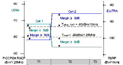
Figure 1 Signal levels and thresholds in the handover test process
3.1 Handover criterion
The handover criterion for the test is as such:
Serving cell signal is changed to lower than threshold Tused with enough margin and neighbour cell signal is changed to higher than threshold Tother_RAT with enough margin at start of T2.
The UE will detect these conditions and will trigger an event 3a report.
After received the event 3a report, SS sends RRC message implying handover.
The UE will transmit PRACH preamble on cell 2 with allowed delay after received handover signal.
3.2 Test case verdict
The design of the test case relies on the UE being able to measure P-CCPCH RSCP and RSRP within accuracy requirements during T1 and T2, and correctly compare it to the signal thresholds.
A detailed analysis of the test case is given in section 5 of this document.
4 Choice and values of uncertainties to be specified
The SS provides two cells on different frequencies with AWGN. We propose to control the following parameters:
AWGN absolute power on cell 1 frequency, Ioc ± 0.7dB
AWGN absolute power on cell 2 frequency, Noc ± 0.7dB
Ratio of cell 1 signal / AWGN, Îor / Ioc ± 0.3dB
Ratio of cell 1 code level / Ior , Ec / Ior ± 0.1dB
Ratio of cell 2 signal / AWGN, Ês / Noc ± 0.3dB
This choice forms a minimum set, so the superposition principle can be applied if necessary. For the test case, the signals are not faded, and the values for Îor / Ioc and Ês / Noc are chosen to be similar to equivalent parameters in W-CDMA, as ±0.3dB. The absolute levels of Ioc and Noc is specified as ± 0.7dB, similar to the uncertainty for other absolute power values such as RefSens. The value for Ec / Ior is specified as ± 0.1dB, similar to the uncertainty in UTRA TDD test specification TS 34.122.
5 Calculation of Test Tolerances
General approach
The general approach is given in the steps below:
Copy the originally specified key parameters from the core requirements
Where relevant, calculate derived parameters from the core requirements
Define uncertainties for a minimum set of parameters
Define controlled parameters (critical to the test verdict), calculate sensitivity factors and uncertainty
Determine which original or derived parameters to offset (apply Test Tolerances to) and by how much
Recalculate original or derived parameters including Test Tolerances
Check that the controlled parameters meet requirements to get the correct test verdict
Each step is explained below, and the calculations are given in the accompanying spreadsheet.
a) Original specified key parameters
The key parameters are copied from Tables 8.3.3a.2 and 8.3.3a.3 in TS 34.122 modified as describing in section 2. The key parameters are selected as the minimum set to define the cell power levels, and which are subject to a test system uncertainty which may affect the verdict of the test. Some signalled parameters threshold Tused and Tother_RAT are also copied, although these are not subject to uncertainty.
The key parameters appear in section a) of the accompanying spreadsheet. The layout for Cell 1 and Cell 2 are similar to tables 8.3.3a.2 and 8.3.3a.3 in TS 34.122, but the AWGN is given a separate set of columns for each frequency. This allows the spreadsheet calculations to be done in a consistent way.
b) Derived parameters
A number of derived parameters are calculated, using the base information in a). The reason for deriving each additional parameter is given in the “Comment” column of section b) in the accompanying spreadsheet.
In this test case, the UE compares RSCP value to threshold Tused and RSRP value to threshold Tother_RAT, so a further step is done to calculate the difference between RSCP/RSRP and their thresholds:
(RSCP – Tused)
(RSRP – Tother_RAT)
c) Uncertainties
The choice of uncertainties is covered in section 4 of this document. They appear in section c) of the accompanying spreadsheet.
In addition the UE measurement accuracies need to be considered, it has some inaccuracy which could affect the test verdict.
For UTRAN TDD P-CCPCH RSCP measurement accuracy TS 25.123 clause 9.1.1.1.1.2 is given in the following extract:
9.1.1.1 P-CCPCH RSCP (TDD)
These measurements consider P-CCPCH RSCP measurements for TDD cells.
The measurement period for CELL_DCH and CELL_FACH state state can be found in section 8.
9.1.1.1.1 Absolute accuracy requirements
<<Some clauses skipped>>
9.1.1.1.1.2 1.28 Mcps TDD option
The accuracy requirements in table 9.1A are valid under the following conditions:
P-CCPCH RSCP -102 dBm
P-CCPCH Ec/Io > -8 dB
DwPCH_Ec/Io > -5 dB
Table 9.1A: P-CCPCH_RSCP absolute accuracy
Parameter |
Unit |
Accuracy [dB] |
Conditions |
|
Normal condition |
Extreme condition |
Io [dBm/ 1.28 MHz] |
||
P-CCPCH_RSCP |
dBm |
6 |
9 |
-94...-70 |
dBm |
8 |
11 |
-70...-50 |
|
For E-UTRAN RSRP measurement accuracy TS 25.123 clause 9.1.1.5a refers to the inter-frequency requirements in TS 36.133, and the relevant clause is 9.1.3 as given in the following extract:
9.1.3 Inter-frequency RSRP Accuracy Requirements
9.1.3.1 Absolute RSRP Accuracy
The requirements for absolute accuracy of RSRP in this section apply to a cell that has different carrier frequency from the serving cell.
The accuracy requirements in Table 9.1.3.1-1 are valid under the following conditions:
Cell specific reference signals are transmitted either from one, two or four antenna ports.
Conditions defined in 36.101 Section 7.3 for reference sensitivity are fulfilled.
RSRP|dBm -127 dBm for Bands 1, 4, 6, 10, 11, 18, 19, 21, 33, 34, 35, 36, 37, 38, 39, 40,
RSRP|dBm -126 dBm for Bands 9,
RSRP|dBm -125 dBm for Bands 2, 5, 7,
RSRP|dBm -124 dBm for Bands 3, 8, 12, 13, 14, 17, 20.
Table 9.1.3.1-1: RSRP Inter frequency absolute accuracy
Parameter |
Unit |
Accuracy [dB] |
Conditions1 |
||||
Normal condition |
Extreme condition |
Bands 1, 4, 6, 10, 11, 18, 19, 21, 33, 34, 35, 36, 37, 38, 39, 40 |
Bands 2, 5, 7 |
Bands 3, 8, 12, 13, 14, 17, 20 |
Band 9 |
||
Io |
Io |
Io |
Io |
||||
RSRP for Ês/Iot -6 dB |
dBm |
6 |
9 |
-121dBm/15kHz … -70dBm/ BWChannel |
-119dBm/15kHz … -70dBm/ BWChannel |
-118dBm/15kHz … -70dBm/ BWChannel |
-120dBm/15kHz … -70dBm/ BWChannel |
RSRP for Ês/Iot -6 dB |
dBm |
8 |
11 |
-70dBm/ BWChannel … -50dBm/ BWChannel |
-70dBm/ BWChannel … -50dBm/ BWChannel |
-70dBm/ BWChannel … -50dBm/ BWChannel |
-70dBm/ BWChannel … -50dBm/ BWChannel |
Note 1. Io is assumed to have constant EPRE across the bandwidth. |
|||||||
For P-CCPCH RSCP measurement, the ±8dB applies during T1 because the Cell 1 Io is between -70dBm and -50dBm, and the ±6dB applies during T2 and T3 because the Cell 1 Io is between -94dBm and -70dBm. Normal conditions are used for the test.
For RSRP measurement, the ±8dB applies during T1, T2 and T3 because the Cell 2 Io is between -70dBm and -50dBm. Normal conditions are used for the test.
d) Controlled parameters critical to verdict
A diagram giving the Cell 1 and Cell 2 signal level during T1, T2 and T3 is provided in section 3 of this document. It also includes the relevant thresholds. This is the most appropriate view to analyse the critical parameters for this test.
From 34.122 clause 8.3.3a.
During T1, the UE has connected with Cell 1, and is required to measure serving Cell 1 and neighbour Cell 2. But event report can not be triggered. The conditions are:
The serving Cell 1 is good enough, expressed as RSCP ≥ Tused with a margin of at least 8dB.
The neighbour cell 2 is bad enough, expressed as RSRP ≤ Tother_RAT with a margin of at least 8dB.
Cell 1 must meet the P-CCPCH RSCP and DwPCH side conditions (level, Ec/Io) in TS 25.123 clause 9.1.1.1.1.2.
Cell 2 must meet the RSRP and SCH side conditions (level, Es/Iot) in TS 36.133 clause 9.1.3.
During T2, the UE is required to send an event 3a trigger report. The conditions are:
The serving Cell 1 must be bad enough, expressed as RSCP < Tused with a margin of at least 6dB.
The neighbour cell 2 is good enough, expressed as RSRP > Tother_RAT with a margin of at least 8dB.
Cell 1 must meet the P-CCPCH RSCP and DwPCH side conditions (level, Ec/Io) in TS 25.123 clause 9.1.1.1.1.2.
Cell 2 must meet the RSRP and SCH side conditions (level, Es/Iot) in TS 36.133 clause 9.1.3.
During T3, the UE is required to do handover, and send uplink signal on Cell 2. The conditions are same as During T2.
The critical conditions are related to the 9 controlled parameters listed in section d) of the accompanying spreadsheet. They have been derived by study of the test case diagram and by careful reading of the relevant clauses in TS 36.133 and TS 25.123. The reason for each parameter being critical to the test verdict is given briefly in the “Comment” column of section d) in the accompanying spreadsheet. Information about the value to be achieved is given later in the “Comment” column of section g) in the spreadsheet.
Having identified the parameters critical to the test verdict which need to be controlled, we now need to consider how they are affected by the parameters which can be set by the test equipment. The sensitivity factors are the ratio (effect on a critical parameter y / a test equipment uncertainty x), and are usually in dB/dB. In this RRM test case there is a simple one-to-one relationship between the parameters that can be set by the test equipment, and their effect on parameters determining the test verdict. The sensitivity factors are therefore derived by inspection as one or zero.
For example, an error of 1dB in the absolute AWGN level Noc would cause 1dB error in the Cell 2 RSRP, so the sensitivity factor is 1.000 during T1, T2 and T3. It would also cause 1dB error in the derived parameter (Cell 2 RSRP - Tother_RAT), so the sensitivity factor is also 1.000 during T1, T2 and T3. However the same error of 1dB in the absolute AWGN level Noc would cause no change to Cell 2 Es/Iot, because all other powers are specified relative to Noc, so the sensitivity factor is zero.
In some cases, the sensitivity factor is an intermediate value. For example, the Cell 1 Ior/Ioc has an effect on P-CCPCH_Ec/Io which depends on ratios of the powers making up the total. In such cases a sensitivity factor value between 0 and 1 results. It is important to calculate these correctly to obtain the overall uncertainty.
For example,
• During T1, the effect of Cell 1 Ior/Ioc uncertainty on Cell 1 P-CCPCH_Ec/Io is x 0.074
These factors can also be derived intuitively, by considering the relative powers in step b). For example, Ioc forms 7.4% / (7.4%+92.6%) of the total power Io, which is 0.074. A change in the Cell 1 Ior/Ioc has very little effect on the ratio of P-CCPCH power to overall power, because the Ior makes up most of the overall power.
Having filled in the matrix of sensitivity factors, the accompanying spreadsheet calculates the overall uncertainty for each controlled parameter, taking into account the uncertainties and sensitivity factors for each parameter that can be set by the test equipment. This process follows the superposition principle. More details and explanation can be found in section 4 of TS 34.902. Uncertainties are calculated separately for T1, T2 and T3.
The normal procedure of combining uncorrelated uncertainties root-sum-square is followed.
When the test system uncertainties and the UE reporting accuracies are combined, the (root-sum square of test system uncertainties) is added arithmetically to the UE reporting accuracies. If all the uncertainties were combined root-sum square, the resulting smaller test limits could case a conformant test system to fail a conformant UE, which would be unacceptable.
e) Determine parameters to offset
For Cell 1:
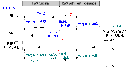
During T2 and T3 (Cell 1 RSCP – Tused) is -6dB, just meeting the margin of at least -6dB. The Ioc of cell 1 is therefore decreased by the Cell 1 RSCP uncertainty. Additionally decreased by the P-CCPCH_Ec/Io uncertainty is not needed due to the minimum Cell 1 P-CCPCH_Ec/Io is -7.99dB take into account of it’s uncertainty, it is bigger than the condition of P-CCPCH_Ec/Io -8 dB in TS 25.123.
During T1, the Ioc is set same as during T2 and T3 to simplify the test.
During T1, the signal (RSCP) of Cell 1 is set to be above Tused with a margin of 8dB, just meeting the margin of at least 8dB. To maintain the 8dB margin, Ior/Ioc of cell 1 is increased by the Ioc reduction, and additionally increased by the Cell 1 RSCP uncertainty.
For Cell 2:
During T1 (Cell 2 RSRP – Tother_RAT) is -8dB, just meeting the margin of at least -8dB. The Noc of cell 2 is therefore decreased by the Cell 2 RSRP uncertainty. Additionally decreased by the Ês/Noc uncertainty is not needed due to the minimum Cell 2 Ês/Iot is -3.33dB take into account of it’s uncertainty, it is bigger than the condition of Ês/Iot -4 dB in TS 36.133.
During T2 and T3, the Noc is set same as during T1 to simplify the test.
During T2 and T3, the signal (RSRP) of Cell 2 is set to be above Tother_RAT with a margin of 8dB, just meeting the margin of at least 8dB. To maintain the 8dB margin, Ês/Noc of cell 2 is increased by the Noc reduction, and additionally increased by the Cell 2 RSRP uncertainty.
The strategy for determining the parameters to offset is shown in the following diagram for T2 and T3 time period as example:
The check that all other controlled parameters meet their required range is done in step g). In theory it is possible for steps e) to g) to be iterative, or possibly even steps c) to g) to be iterative, but this test case can be done without such iteration.
f) Parameters modified by Test Tolerances
Based on the decision in e), the set of parameters in a) and b) is reproduced in section f) of the accompanying spreadsheet, but this time modified by the Test Tolerances (applied offsets).
Re-derived parameters are calculated using the same methods as were used in step b).
g) Check controlled parameters Min/Max
Using a format similar to that in step d), the nominal value of each controlled parameter is recalculated, as at least some will have changed from the original due to the application of the Test Tolerances in step f).
The minimum and maximum values, due to variability from uncertainties, of controlled parameters is then calculated and compared against the requirements (Required margin relative to threshold, Es/Iot range, RSRP level..). It is not necessary to calculate all parameters during each time interval T1, T2 and T3, so a selection is made of those critical to the test verdict. The critical requirement for each parameter is given briefly in the “Comment” column of section g) in the accompanying spreadsheet. The cases closest to limit (in these test cases, all limits are one-sided) are identified by turquoise cells in the spreadsheet. If all requirements are met, then the exercise is complete.
It can be seen that with the uncertainty values and Test Tolerances proposed, all the requirements are met.
Version Control
Version Control
Toto je jediná verze této specifikace.
Download & Access
34902-950.zip
Technical Details
AI Classification
Version Information
Document Info
Keywords & Refs
Partners
File Info
3GPP Spec Explorer - Enhanced specification intelligence