Description
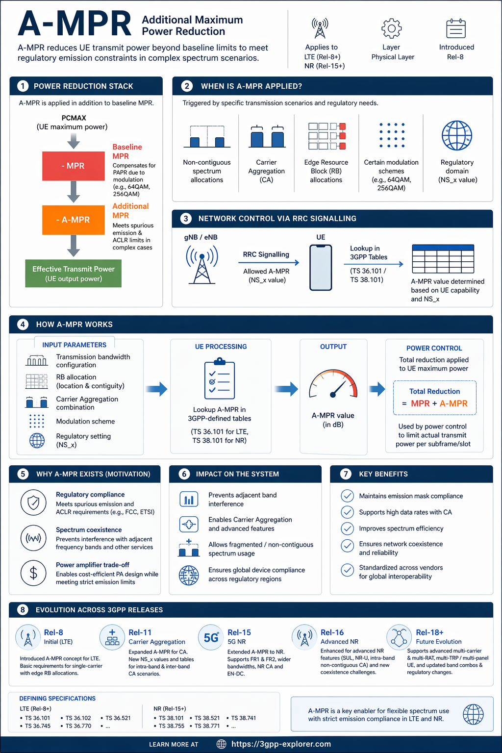
Additional Maximum Power Reduction (A-MPR) is a standardized mechanism defined in 3GPP specifications that allows a User Equipment (UE) to apply an extra power reduction on top of the baseline Maximum Power Reduction (MPR). The baseline MPR is applied to account for the increased Peak-to-Average Power Ratio (PAPR) when using higher-order modulation schemes like 64QAM or 256QAM. A-MPR addresses more specific and stringent regulatory requirements, particularly those related to spurious emissions and the Adjacent Channel Leakage Ratio (ACLR). These requirements become especially challenging when the UE operates in non-contiguous spectrum allocations, uses certain Resource Block (RB) allocations at the edge of a carrier, or employs Carrier Aggregation (CA) where multiple component carriers are active simultaneously.
The application of A-MPR is not universal but is triggered by specific network signaling. The network configures the UE with an 'Allowed A-MPR' value through RRC signaling, typically within the RadioResourceConfigDedicated or similar information elements. This configuration includes parameters such as the network signaling value (NS_x), which corresponds to a specific set of regional regulatory requirements (e.g., FCC, ETSI). The UE, based on its implemented capabilities and the signaled NS_x value, determines the applicable A-MPR value from predefined tables in the specifications (e.g., 3GPP TS 36.101 for LTE, TS 38.101 for NR). The UE then applies this A-MPR value in addition to any baseline MPR, effectively lowering its maximum transmit power (PCMAX) to ensure its transmitted signal remains within the mandated emission masks.
The technical implementation involves complex lookup tables that map various transmission parameters to a required A-MPR value. These parameters include the transmission bandwidth configuration, the location and contiguity of the allocated resource blocks, the modulation scheme, and the specific CA band combination. For example, a UE transmitting on two non-adjacent component carriers in Band 1 and Band 3 might require a higher A-MPR than if it were transmitting on a single contiguous block. The UE's power control algorithm must dynamically calculate the total maximum power reduction (MPR + A-MPR) to determine the permissible maximum output power for each subframe or slot, ensuring real-time compliance.
A-MPR plays a vital role in the radio access network's physical layer by enabling flexible spectrum usage while protecting the integrity of the radio spectrum. Without it, aggressive spectrum re-farming, carrier aggregation, and the use of fragmented spectrum blocks could lead to unacceptable levels of out-of-band emissions, causing interference to services in neighboring bands. By defining clear, testable requirements for A-MPR, 3GPP ensures that UEs from different vendors can interoperate in networks worldwide, all while adhering to diverse and strict regional regulatory regimes. Its proper implementation is verified through rigorous conformance testing defined in specifications like TS 36.521 and TS 38.521.
Purpose & Motivation
A-MPR was created to solve the practical problem of operating modern, high-throughput cellular systems within strict regulatory emission limits, especially as spectrum usage became more complex. Early 3GPP releases (pre-Rel-8) dealt with relatively simple, contiguous spectrum allocations. However, with the introduction of LTE in Rel-8 and the subsequent push for higher data rates, techniques like carrier aggregation and the use of non-contiguous spectrum blocks became essential. These advanced transmission scenarios create more challenging signal waveforms with sharper transitions and higher spectral regrowth, making it harder for UE power amplifiers to maintain clean emissions outside the assigned channel. The baseline MPR, designed for modulation-based power back-off, was insufficient to meet the spurious emission and spectrum emission mask requirements mandated by national regulators (e.g., FCC, ETSI) for these complex cases.
The primary motivation was regulatory compliance and spectrum coexistence. Without A-MPR, a UE operating with carrier aggregation at the edge of its operating band could emit excessive power into an adjacent band, potentially interfering with another operator's network or a completely different service (e.g., aviation, satellite). This would violate licensing conditions and degrade overall network performance. A-MPR provides a standardized, network-controlled method to mandate additional power back-off precisely when and where it is needed. This allows network operators to deploy advanced features confidently, knowing that UEs will automatically adjust their power to stay within legal limits, regardless of the specific resource allocation or band combination in use.
Furthermore, A-MPR addresses the economic and technical challenge of UE power amplifier design. Designing a power amplifier that never exceeds emission limits under all possible transmission scenarios would be prohibitively expensive and inefficient. A-MPR offers a compromise: the amplifier can be designed for typical cases, and for the exceptional, more demanding cases, a controlled reduction in maximum output power is applied. This balances cost, power efficiency (battery life), and regulatory compliance. It represents a key enabler for the global scalability of LTE and NR devices, ensuring a single UE design can adapt its operation through software and configuration to meet the specific emission rules of any country it operates in.
Infographic
Classification
Detected Changes Across Releases
from 3GPP Change RequestsSpecific changes extracted from the „Change history“ tables of 3GPP specifications (37 CRs across 2 releases). Complements the general historical overview above with the evidence-based evolution of this function.
Studied in Rel-8, normative work from Rel-18.
In Release 18, the A-MPR function was updated with specific corrections and new requirements for IoT and NTN operations. This included corrections to the A-MPR requirements for Category M1 UEs, the addition of A-MPR and additional spurious emission arrangements for Non-Terrestrial Networks (NTN), and the introduction of band 254 into relevant test cases. Furthermore, updates were made to the test cases for network signaling value NS_24 and to align certain test frequency ranges with regular LTE UE requirements.
- Updates to the additional emissions requirements related to NS_02N TS 36.102CR0001
- CR to 36.102 for MPR and A-MPR TS 36.102CR0003
- Update A-MPR for NS_24 for Cat-M1 TS 36.102CR0005
- Correction on Pcmax and OOBB requirement for category NB1/NB2 UE TS 36.102CR0010
- CR to remove PC5 for A-MPR table TS 36.102CR0018
- (IoT_NTN_FDD_LS_band-Core) CR to TS 36.102 for additional spurious emission for band 254 TS 36.102CR0030
+ 21 more changes
In Release 19, the A-MPR (Additional Maximum Power Reduction) function was updated with new requirements and test cases specifically for IoT NTN (Non-Terrestrial Networks). Key additions included the introduction of band 252 into A-MPR test cases for category M1 and NB-IoT NTN, alongside clarifications and updates to power back-off simulation results for NTN L-band and S-band operations. Furthermore, the release provided corrections and editorial updates to the network signaling flags and sub-clauses detailing the additional requirements for these IoT NTN bands.
- (IoT_NTN_FDD_LS_band-Core) Correction of the IoT NTN band 254 NS flag references to the sub-clauses with additional requirements TS 36.102CR0080
- Addition of band 252 into A-MPR TC for category M1 and NB-IoT NTN TS 36.521CR0113
- Addition of power class 1 and power class 2 in test case 6.2B.1 UE maximum output power for category NB1 and NB2 TS 36.521CR0119
- Update to A-MPR TCs for NB-IoT NTN band TS 36.521CR0124
- IoT NTN power density tests - MU and TT update TS 36.521CR0126
- Addition of power back-off simulation results for the NTN L-bands TS 38.863CR0043
+ 4 more changes
Explore further
Broader topics and technologies where A-MPR plays a role.
Defining Specifications
3GPP specifications that define or reference A-MPR, with the latest known release. Sourced from the 3GPP document catalog — see methodology.
| Specification | Title | Release |
|---|---|---|
| TS 36.101 vj30 | LTE UE Radio Transmission & Reception Requirements | Rel-19 |
| TS 36.102 vj10 | E-UTRA UE Satellite Access RF Requirements | Rel-19 |
| TS 36.521 vj00 | E-UTRA UE Conformance ICS Proforma | Rel-19 |
| TS 36.745 ve00 | Satellite Protection for LTE Bands 11/21 | Rel-14 |
| TR 36.770 vi00 | Technical Report for High Power UE in LTE Band 14 | Rel-18 |
| TS 36.852 | 3GPP TR 36.852 | Rel-8 |
| TS 36.860 | 3GPP TR 36.860 | Rel-8 |
| TS 36.899 | 3GPP TR 36.899 | Rel-8 |
| TS 37.717 | 3GPP TR 37.717 | Rel-8 |
| TS 37.718 | 3GPP TR 37.718 | Rel-8 |
| TS 37.719 vj00 | 3GPP TR 37.719: Dual Connectivity Band Combinations | Rel-19 |
| TS 37.825 vg00 | High Power UE (PC2) for EN-DC TDD-TDD | Rel-16 |
| TR 37.829 vi00 | Technical Report | Rel-18 |
| TS 37.862 vj00 | Adding channel bandwidth in existing NR bands | Rel-19 |
| TR 37.880 vh20 | High-power UE for fixed-wireless/vehicle use | Rel-17 |
| TR 37.902 vj00 | OTA TRP/TRS Measurement for LTE Terminals | Rel-19 |
| TS 38.101 vj31 | NR User Equipment Radio Transmissions | Rel-19 |
| TS 38.521 vj20 | NR Physical Layer UE Conformance Testing | Rel-19 |
| TS 38.741 vj00 | NTN L-/S-band for NR Technical Specification | Rel-19 |
| TS 38.755 vj10 | NR FR1 DL Fragmented Carriers Study | Rel-19 |
| TS 38.771 vj00 | FR2-1 OTA Testing for STxMP UEs | Rel-19 |
| TR 38.785 vh00 | UE radio transmission for enhanced NR sidelink | Rel-17 |
| TR 38.786 vi20 | Technical Report for NR Sidelink Evolution | Rel-18 |
| TS 38.787 vj00 | UE Radio Transmission for Sidelink CA in ITS Band | Rel-19 |
| TS 38.793 vj00 | Simultaneous Rx/Tx Band Combinations TR | Rel-19 |
| TS 38.795 vj00 | High Power UE Technical Report for NR FR1 | Rel-19 |
| TS 38.796 vj00 | Rel-19 High Power UE for NR FR1 | Rel-19 |
| TS 38.819 vg00 | Band n65 for New Radio Technical Report | Rel-16 |
| TR 38.839 vh00 | Simultaneous Rx/Tx band combinations | Rel-17 |
| TS 38.863 vj10 | NR NTN RF and Co-existence Spec | Rel-19 |
| TR 38.868 vh00 | Optimizations of pi/2 BPSK uplink power in NR | Rel-17 |
| TS 38.873 vg00 | NR Band n48 Technical Report | Rel-16 |
| TR 38.881 vi00 | Technical Report on Lower MSD for Inter-band CA/EN-DC/DC | Rel-18 |
| TR 38.886 vg30 | NR V2X UE Radio Transmission & Reception | Rel-16 |
| TR 38.894 vi00 | Technical Report | Rel-18 |